Forums:
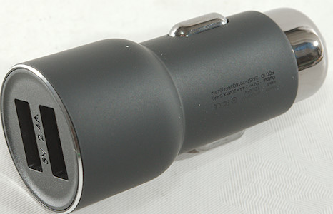
Moxom 2 port KH-25
Official specifications:
- Brand: MOXOM
- Model Numer: KH-25
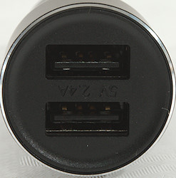
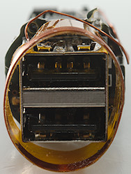
- Output Interface: USB
- USB Ports: 2
- Output: 5V/2.4A
- Input: 100-240V
- Type: AUTO ID 2.4A
- Plug Type: EU Plug
- Plug Diameter: 4mm
I got it from aliexpress dealer: MOXOM Official Store


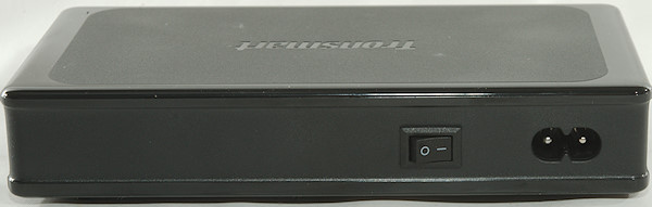
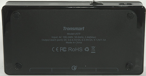
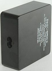
A nice plastic box, but it looks like it has been at a warm place.

The box included the charger and a usb cable.


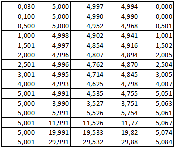
Measurements
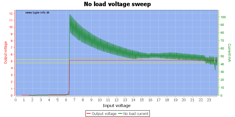
- Power consumption when idle is 0.17 watt
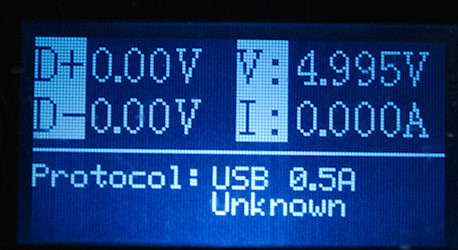
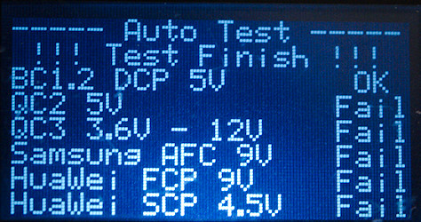
- Android output is coded as usb charger (DCP)
- Apple output is coded as Apple 2.1A
- The two outputs are in parallel.
- Weight: 51.7g
- Size: 90 × 41.6 × 37mm

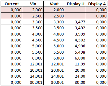
The Android port can deliver about 1.9A

The Apple port is the same.

And together it is also 1.9A

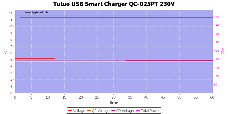
Using 120VAC mains do not change it.

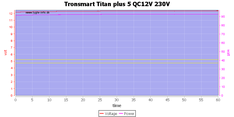
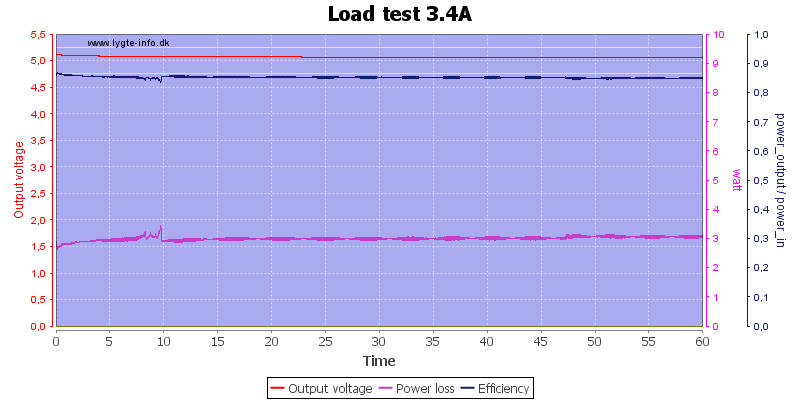
The charger could run for 1 hour delivering 1.8A
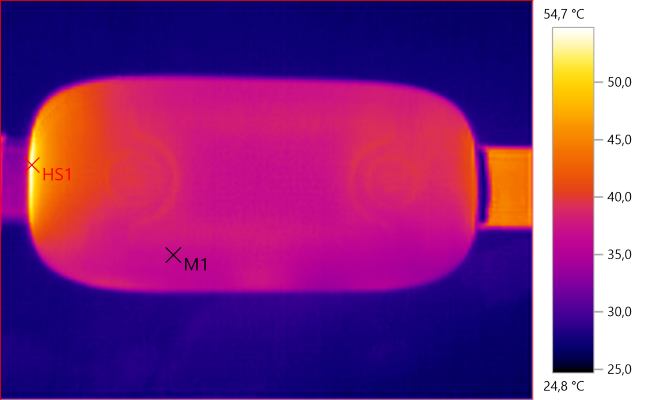
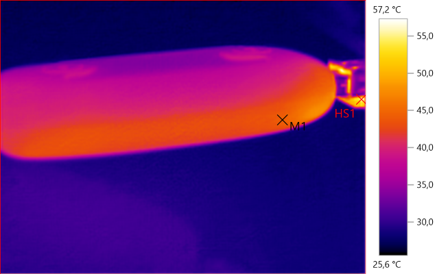
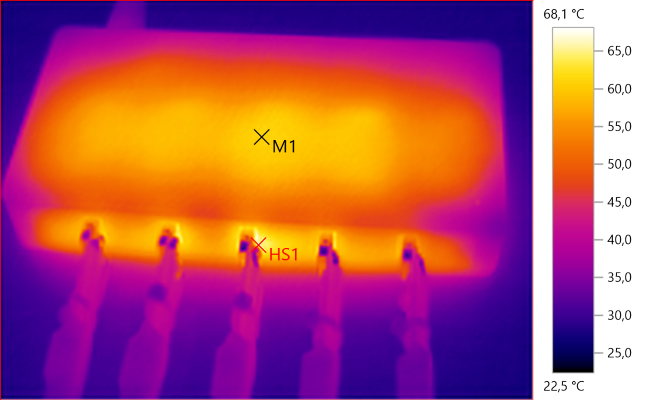
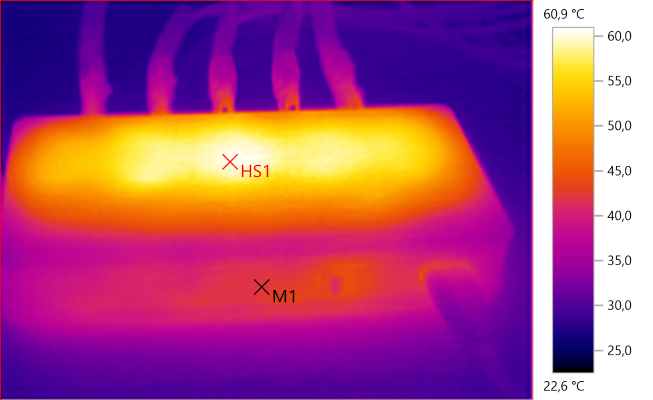
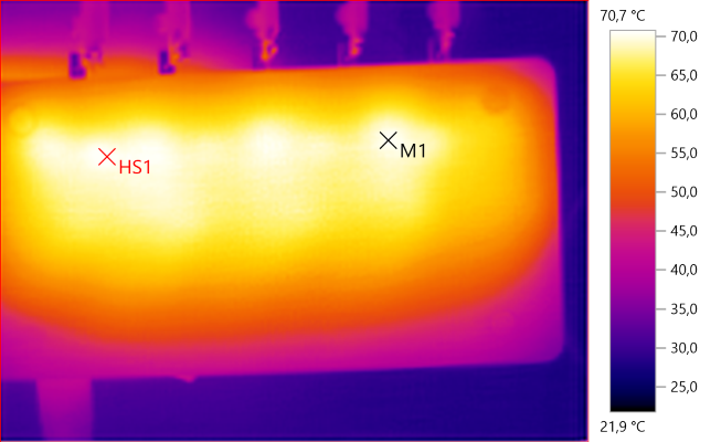
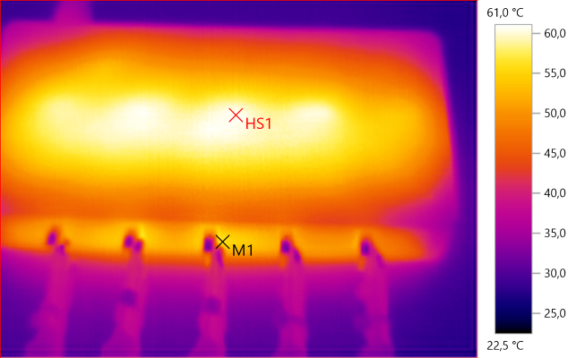
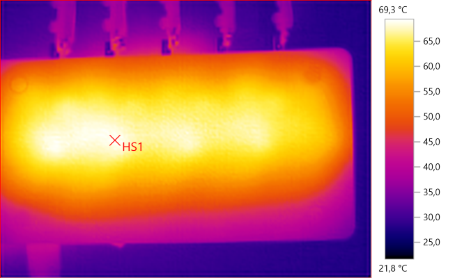
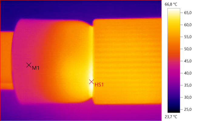
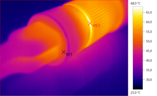
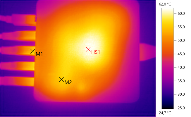
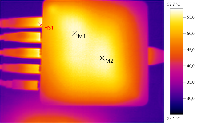
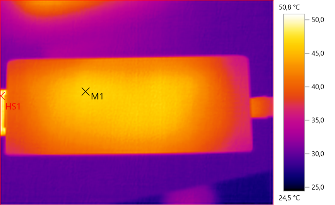
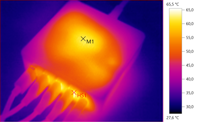
The temperature photos below are taken between 30 minutes and 60 minutes into the one hour test.

M1: 52.0°C, HS1: 56.1°C

HS1: 57.5°C

M1: 52.4°C, HS1: 54.2°C

HS1: 61.3°C

M1: 49.4°C, HS1: 61.4°C

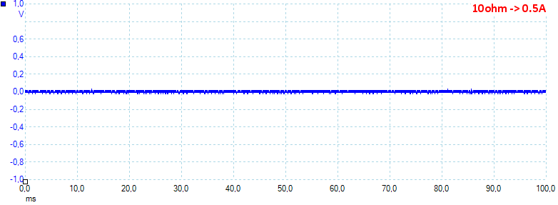
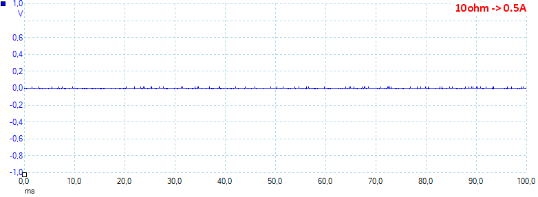
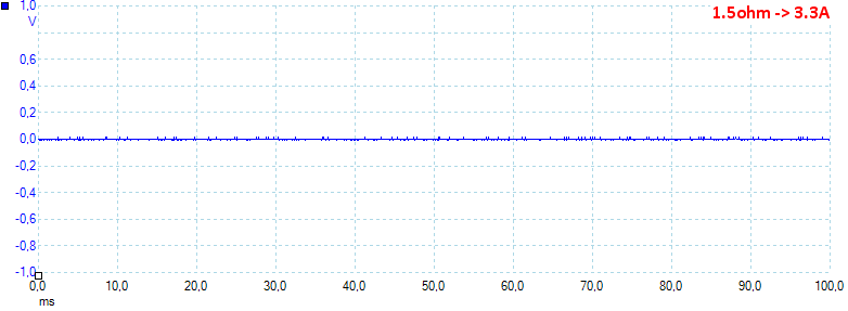
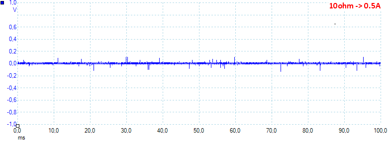
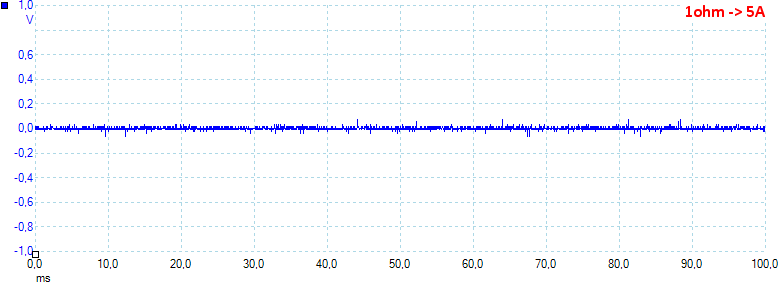
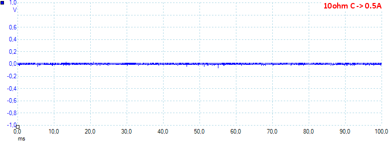
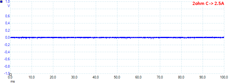
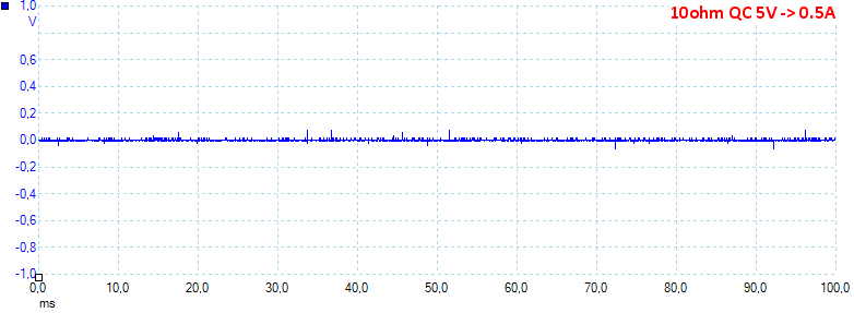
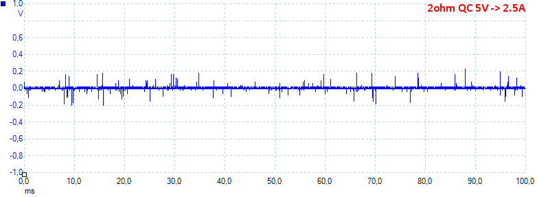
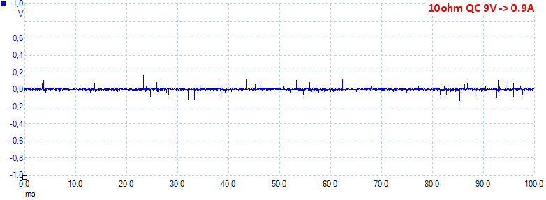
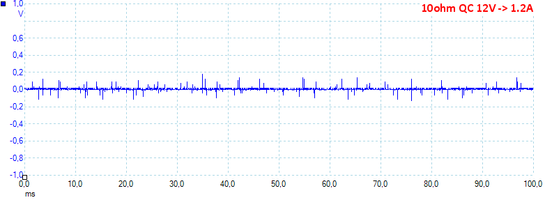
At 0.5A the noise is 35mV rms and 233mVpp.

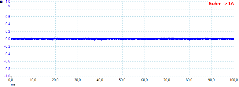
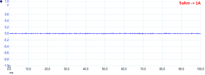
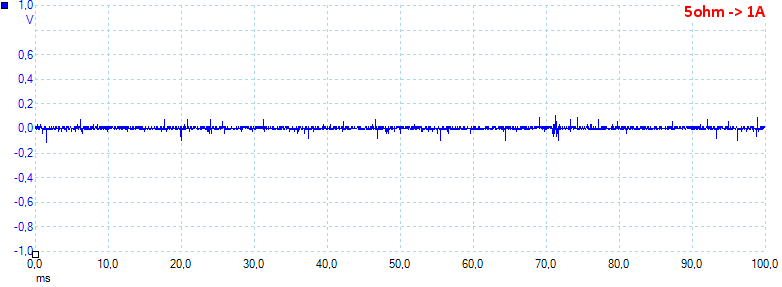
At 1A the noise is 53mV rms and 450mVpp.

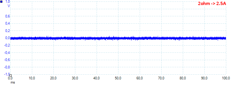
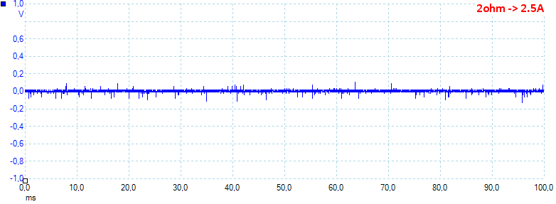
At 2A the noise is 54mV rms and 331mVpp.
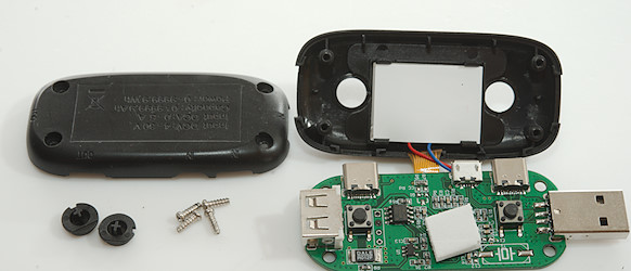
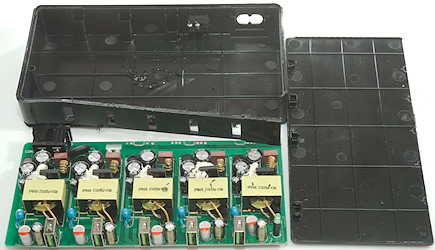
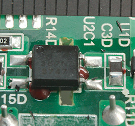
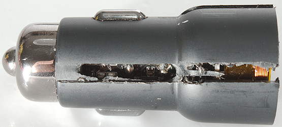
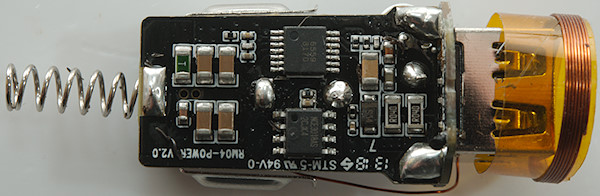
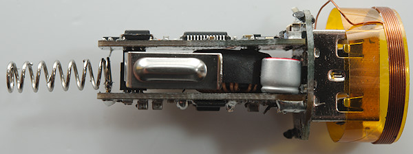
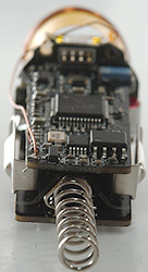
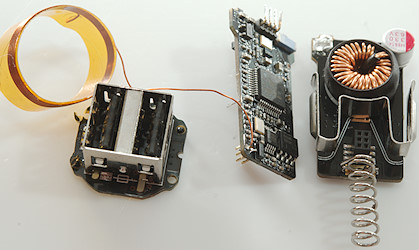
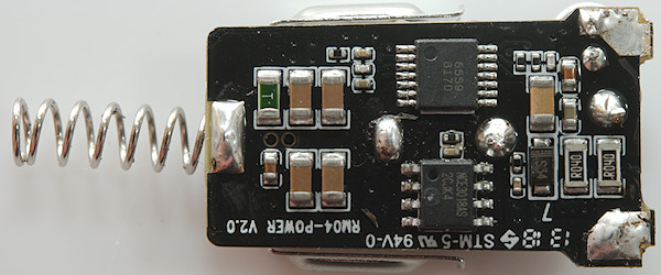
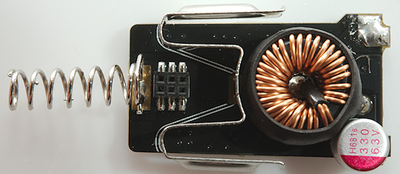
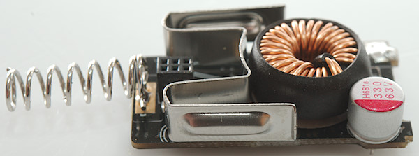
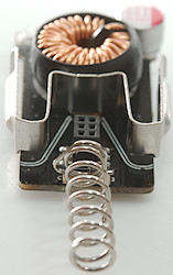
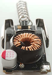
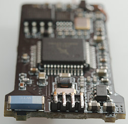
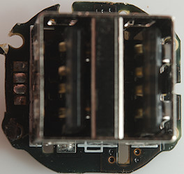
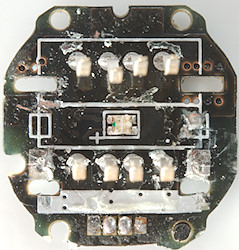
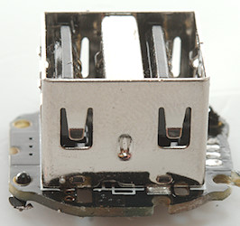
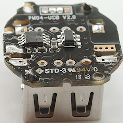
Tear down

Some pressure with my vice at the correct place made the lid pop open.

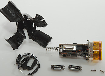
And it was taken apart.

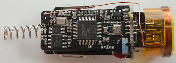
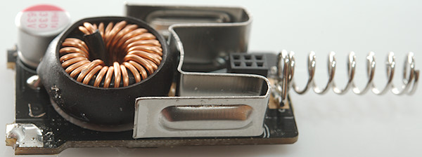
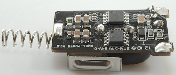
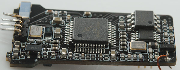
On this side is the fusible resistor at the mains input, a mains switcher, a safety capacitor and the rectifier diode.


On this side is the bridge rectifier and the blue indicator led . The coding resistors for the Apple coding is also here.


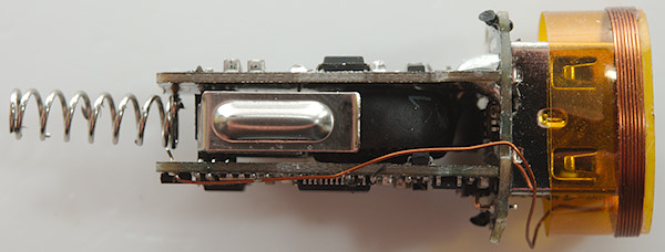
There is a slot in the circuit board, but it would have to be longer to really work, the distance between mains and low volt side is around 2mm, this is way to short.
The charger passed the 2830 volt and 4242 volt test, this means it is it is fairly safe, but as can be seen above it is not safe enough.
Conclusion
The coding is rather old style with fixed Android and Apple, instead of using a DCP coding on both outputs (Apple also knows that coding today), the output current is lower than rated and rather low for a two output charger.
The website shows approval certificates, but they cannot be for this charger with the low distance between mains and low volt side.
The charger do not live up to all the nice work on the website and the box, I will not recommend this charger.
Notes
Index of all tested USB power supplies/chargers
Read more about how I test USB power supplies/charger
How does a usb charger work?
—
My website with reviews of many chargers and batteries (More than 1000): https://lygte-info.dk/