Fury Universal PSU Doctor
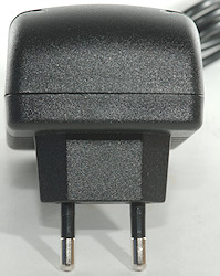
![DSC_9545]()
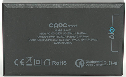
Official specifications:
- Fully supports Smart phones and Tablets (IOS and Android OS) for any brand models and ps3/ps4/xbox360 joypad.
- Autodetect the operating system IOS or Android charging mode and/or Joypad mode.
- Lightweight and easily portable to wherever you are at home, office, traveling or in the car.
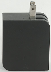
- Dimension: 8.9 (L) * 5.3 (W) * 4.2 (H) cm.
- Weight: 142g
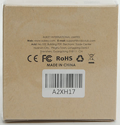
- Rohs Compliant
- CE and FCC Compliant
- Ultra-Low Power Technology
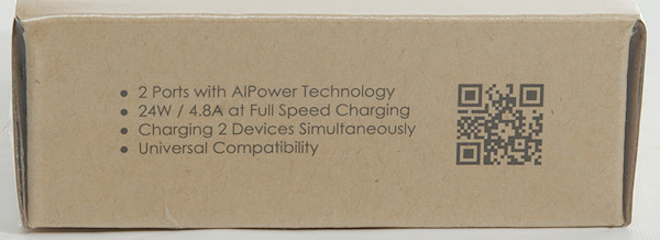
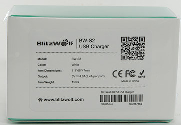
- Output: 5V2.14A, 9V1.6A or 12V1.2A
- A total of 5v 4.2A max output becomes available.
- Stop (RAM retained): 0.23 uA, (LVD enabled): 0.31 uA
- Snooze: 0.7 mA (UART), 1.20 mA (ADC)
- Operating: 63 uA /MHz
- 16-bit RL78 CPU Core
- ADC: Up to 11 channels, 10-bit resolution
- On-chip temperature sensor
- Ripple and Noise: 80mV
- Efficiency: 80%
I got it from HDfury.eu shop.
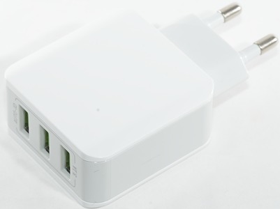
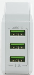
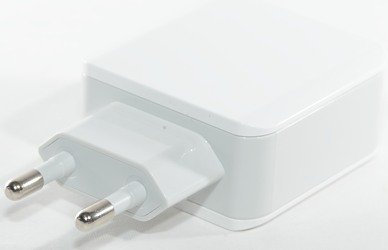
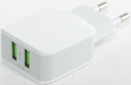
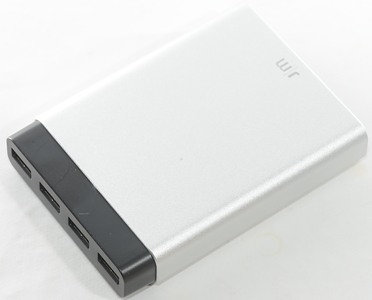
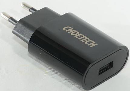
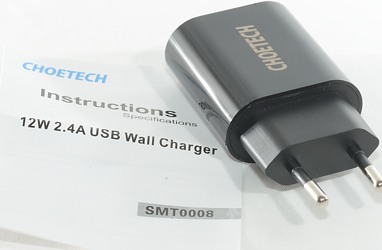
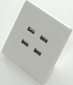
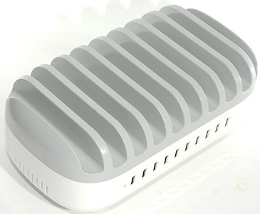
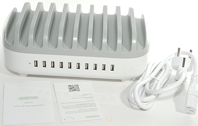
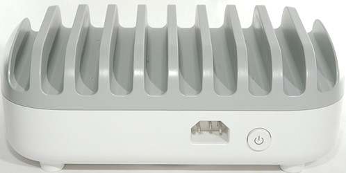
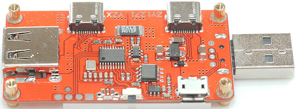
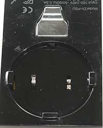
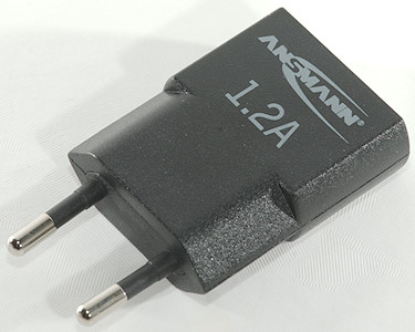
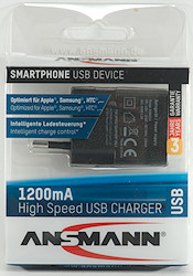
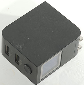
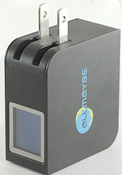
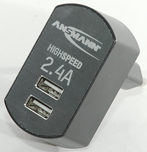
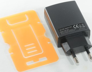
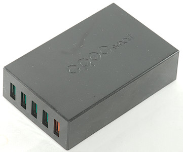
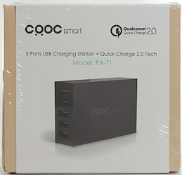
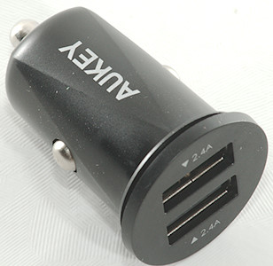
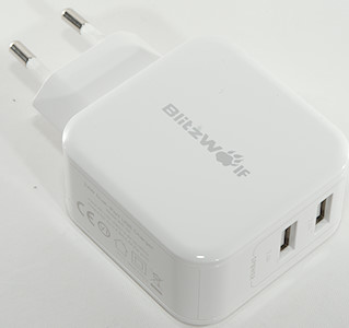
This is a usb charger, that with the help of a smartphone, can show current and voltage for all 3 outputs. This sound like it may be a smart idea.
But the specifications are a bit of nonsense, some of the data looks to cover only the MPU inside the charger and they are basically useless: Knowing the power consumption of the MPU in different modes, is not really useful when not knowing what modes are used and how much, a total power consumption from mains would be better anyway. That the MPU has 11 ADC channels, do not say anything about how many is used.
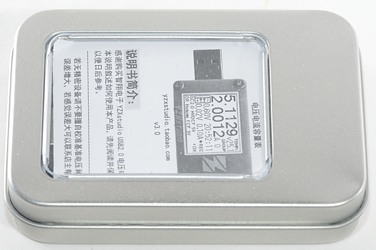
![DSC_9542]()
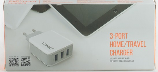
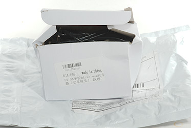
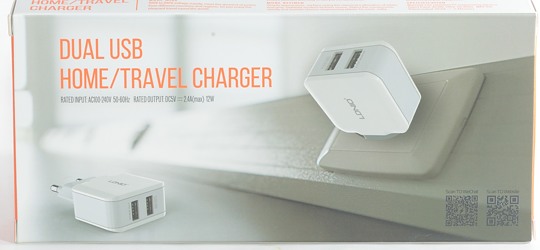
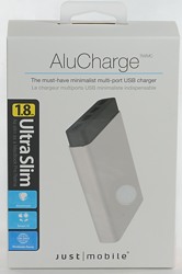
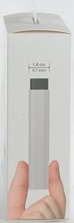
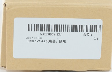
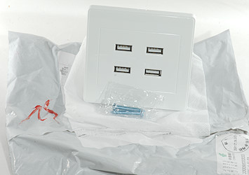
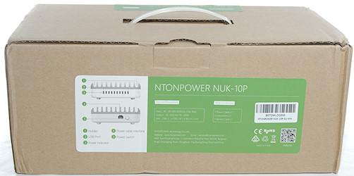
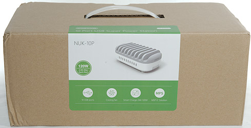
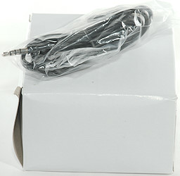
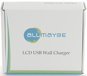
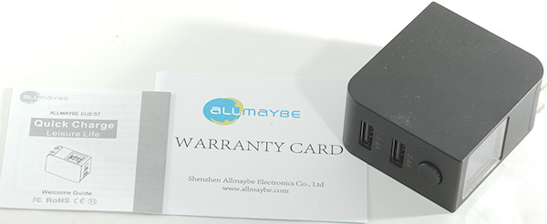
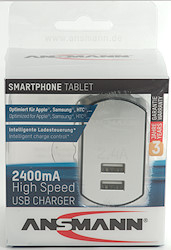
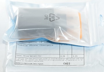
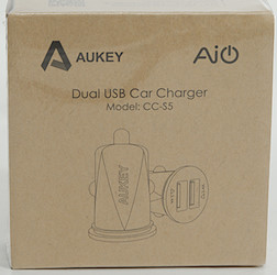
I got it in a cardboard box with a very important cable outside the box.
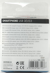
![DSC_9543]()
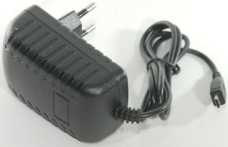
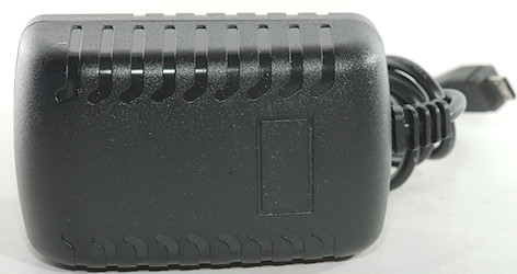
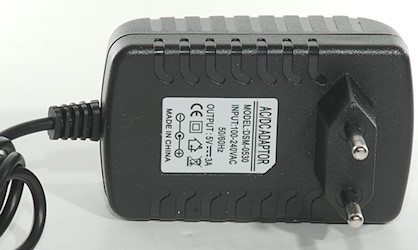
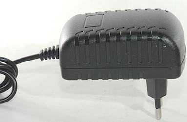
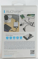
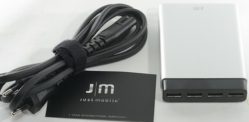
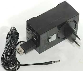
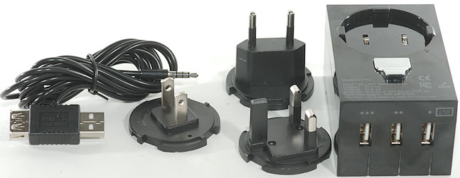
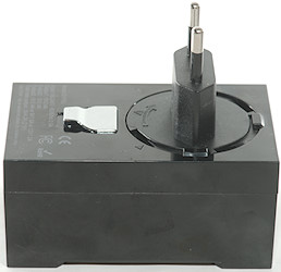
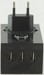
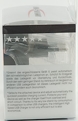
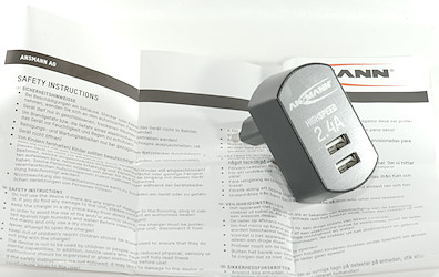
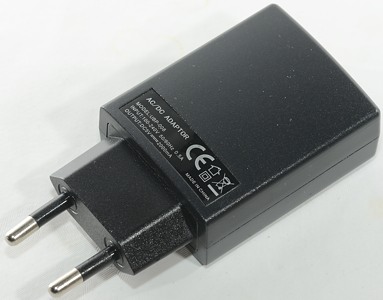
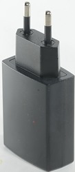
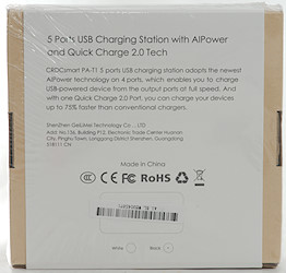
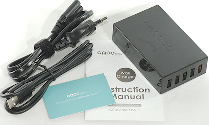
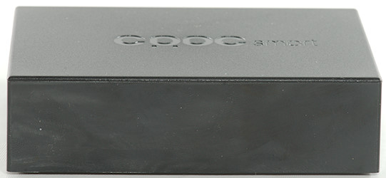
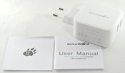
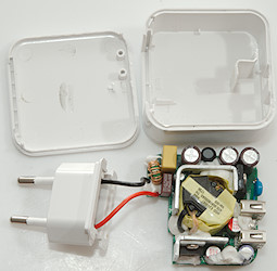
Inside the box was the power supply and a couple of mains adapters. No manual was supplied.
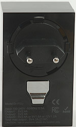
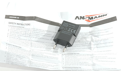
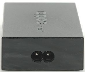
![DSC_9544]()
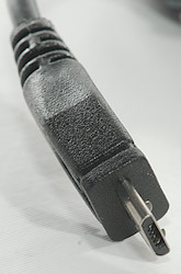
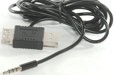
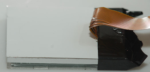
The cable between the power supply and the phone. This uses the headphone jack on the phone to supply data on the microphone input (Remember that not all phones has this jack).
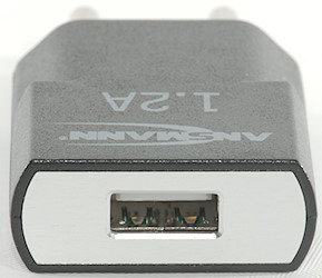
![DSC_9546]()
![DSC_9547]()
![DSC_0078]()
![DSC_9548]()
![DSC_9549]() Application (Android)
Application (Android)
Click on the images to get full size.
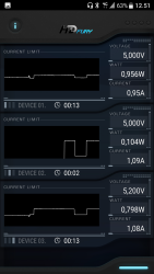
![Screenshot_3]()
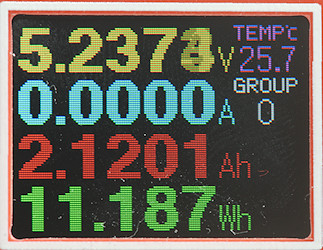
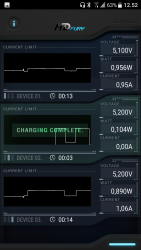
3 devices charging, each at 1A and 5 volt. The WATT label is not watt, but watt hours (Wh).
![Screenshot_4]()
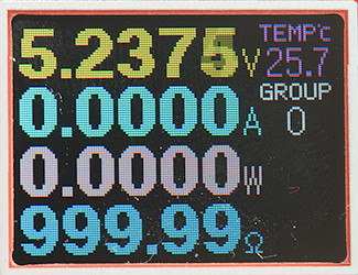
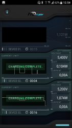
One device has finished charging, this is concluded from the power consumption.
![Screenshot_5]()
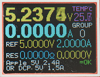
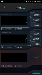
Two devices finished and one output not connected.
![Screenshot_9]()
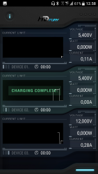
Here I am using Quick Charge on the 3 output, the device is charged with 12V.
![Screenshot_8]()
Overload, I tried charging two devices at 5V 1A and one device at 12V 1A, the power to the 12V device was shut down.
![Screenshot_2]()
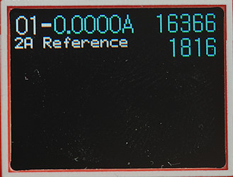
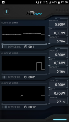
But everything is not fine, here I am drawing 1A, 0.2A and 0.5A. I tried it again at a later time, but there the result was not this bad.
The first channel has been drawing 1A all the time, but as can be seen on the curve the registered current jumps a bit up/down, depending on the load on the other channels.
The chart scale only goes to 2A on the display, this is slightly less in real life due to the errors.
The chart will be cleared when power goes into standby or the application is stopped for any reason.
Watt(Wh) and time is accumulated in the charger and will show correct when the application is started.
Measurements
- Power consumption when idle is 0.14 watt
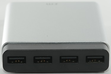
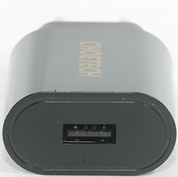
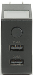
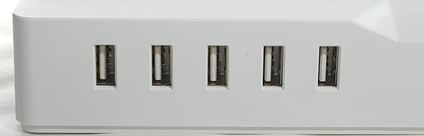
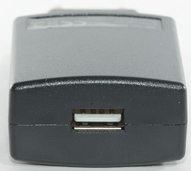
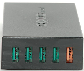
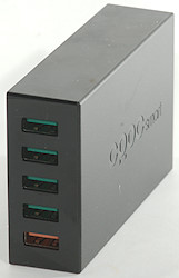
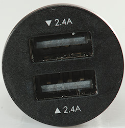
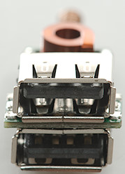
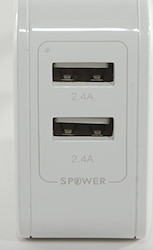
- Usb output #1 is coded as no coding (The data pins are used for communicating with the phone).
- Usb output #2 is coded as Apple 2.1A (There may be some auto coding, but I did not detect it).
- Usb output #3 is coded as Quick Charge 2.0 and auto with Apple 2.1A as max.
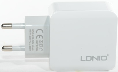
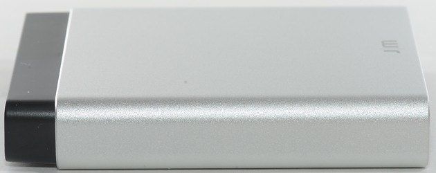
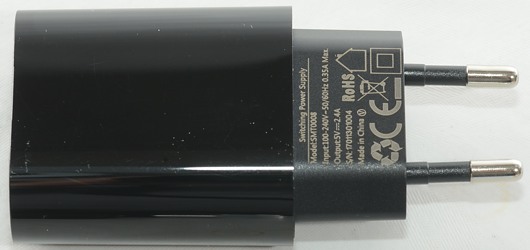
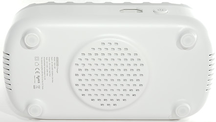
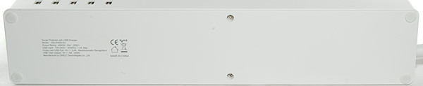
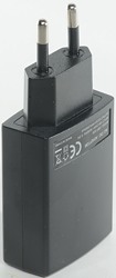
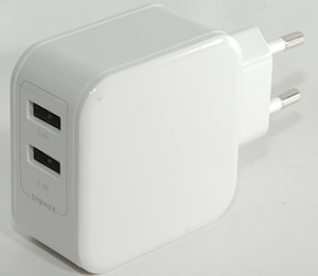
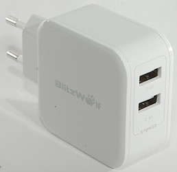
- Weight: 156g (without accessories)
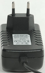
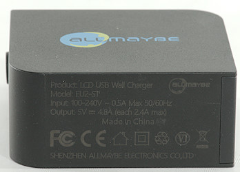
- Size: 89.8 × 81.8 × 54.4mm (EU plug)
- Current resolution is about 0.02A, this fits fine with a 10bit ADC
![CurrentLimits]()
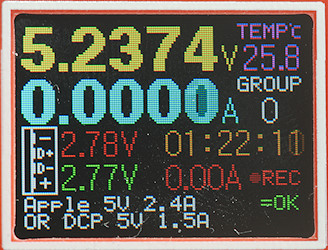
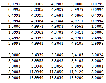
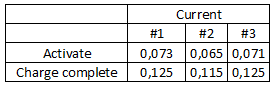
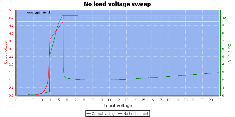
A device must draw about 70mA before it will be registered and anything below about 120mA will report “Charging complete”.
![CurrentMeasurement]()
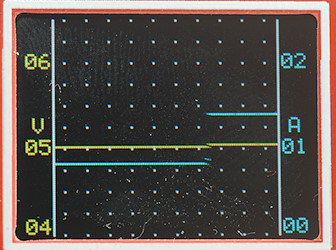
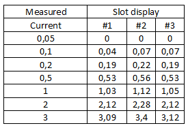
Even when everything is working the current is not that precise.
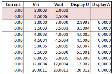
![VoltageMeasurement]()
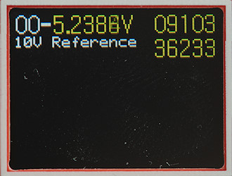
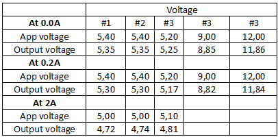
Voltage measurement is also a bit off and fairly high when the device is unloaded.
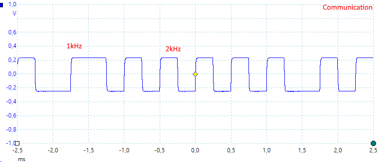
![Comm]()
The communication to the phone is done with audio tones (FSK). I did not see an obvious gab between messages, i.e. the tone must be on all the time.
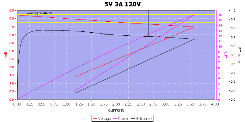
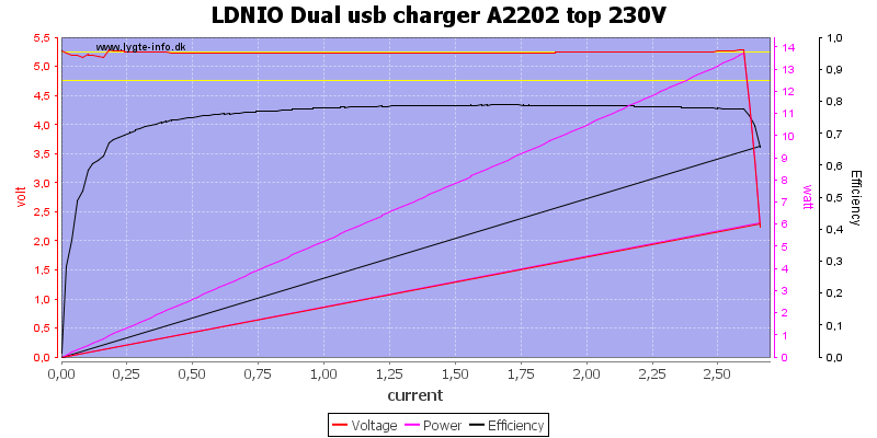
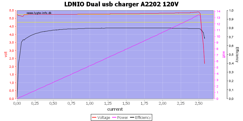
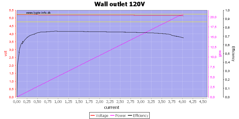
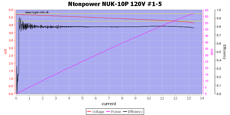
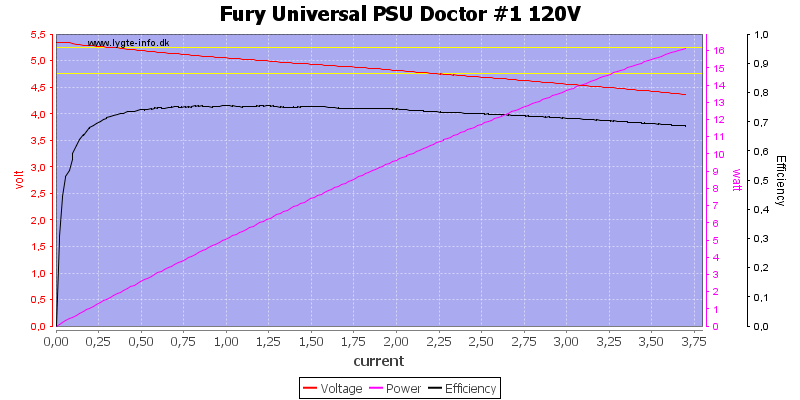
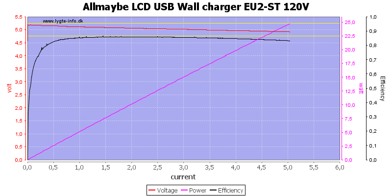
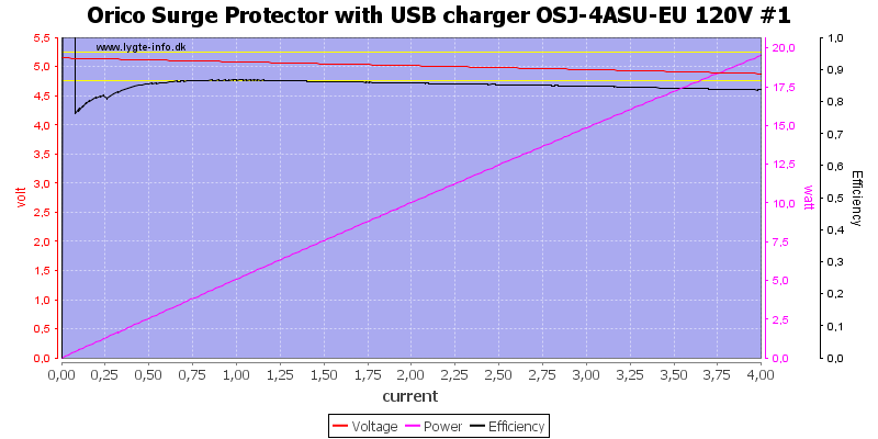
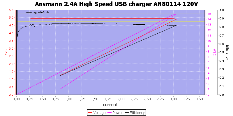
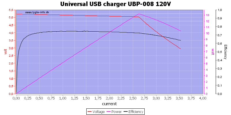
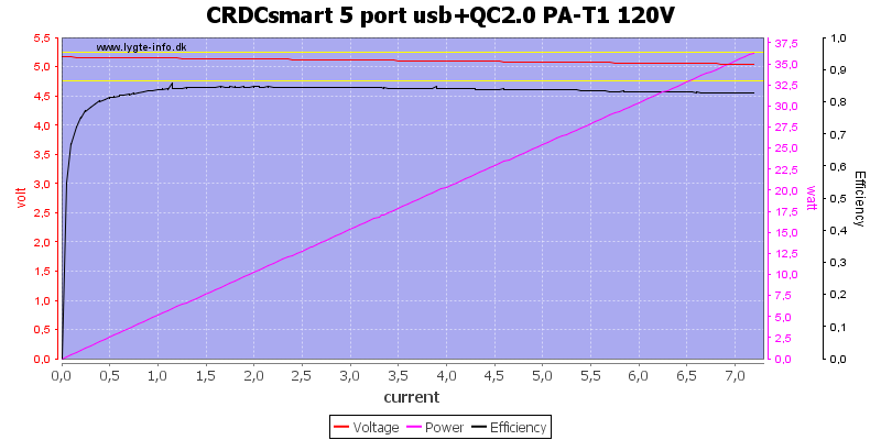
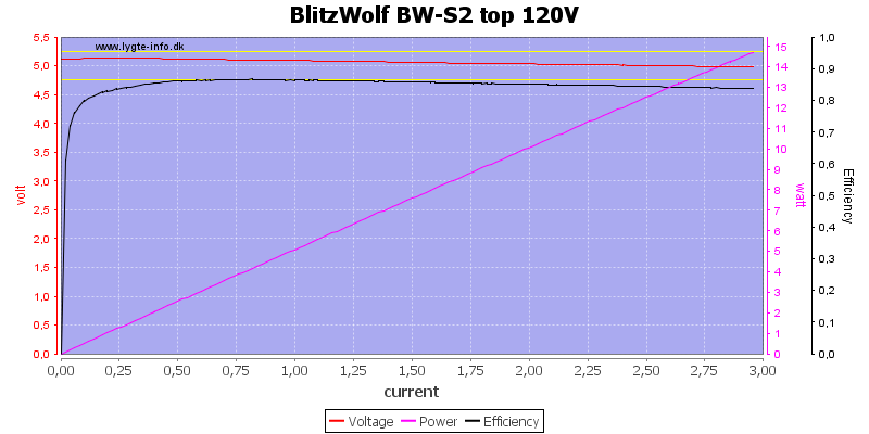
![Fury%20Universal%20PSU%20Doctor%20%231%20120V%20load%20sweep]()
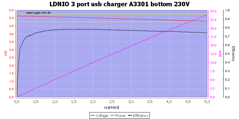
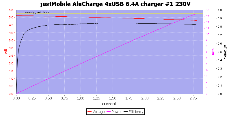
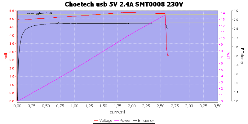
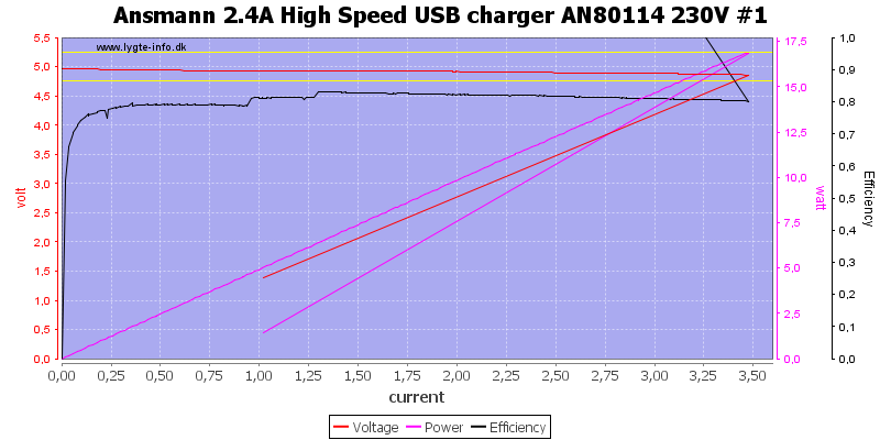
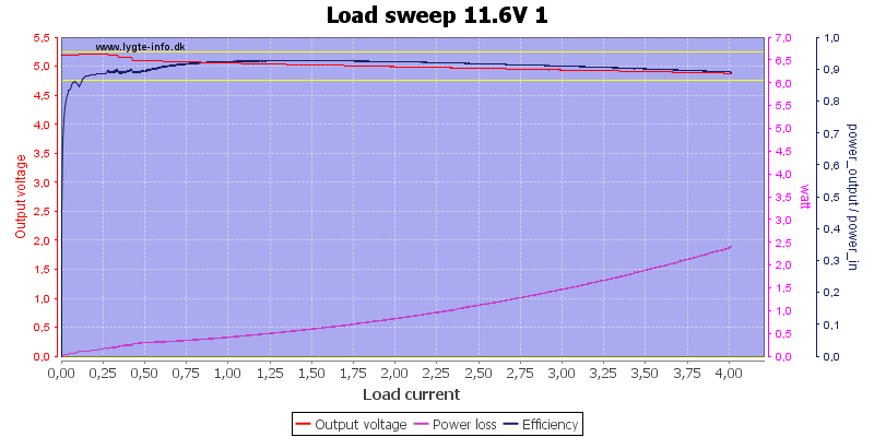
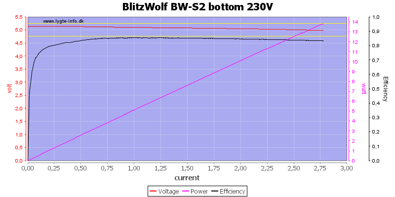
Output #1 can deliver about 3.6A before overload protection kicks in. The output voltage drops significantly with load, this may be due to current sense resistors inside the supply.
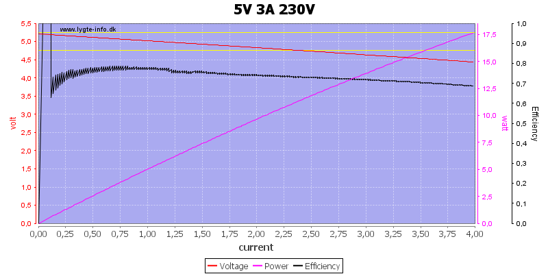
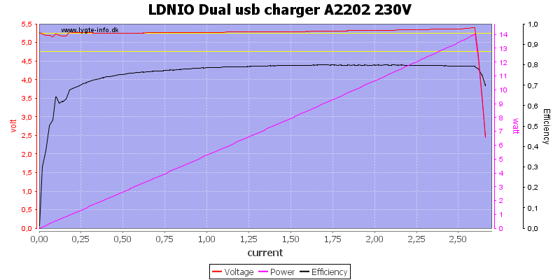
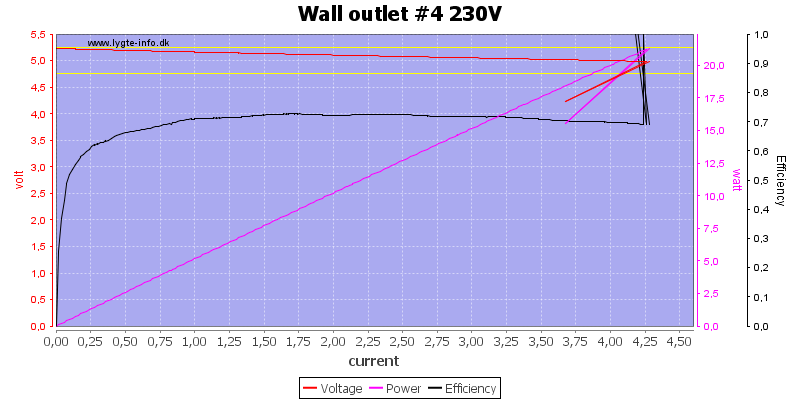
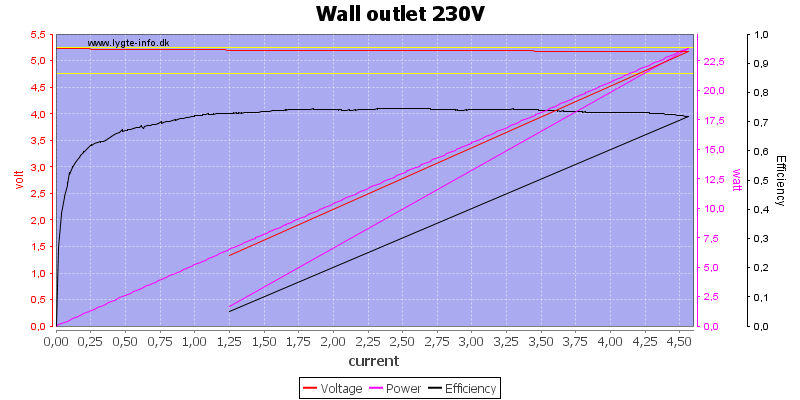
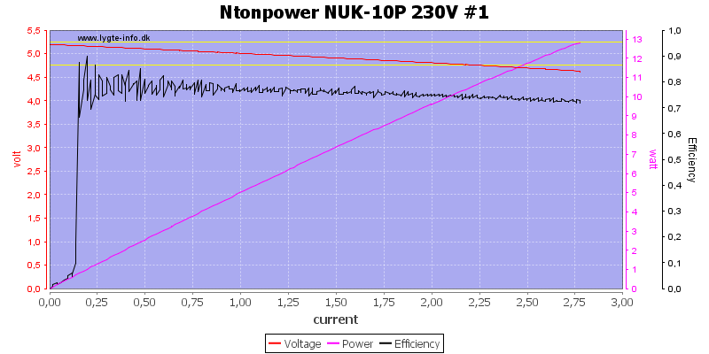
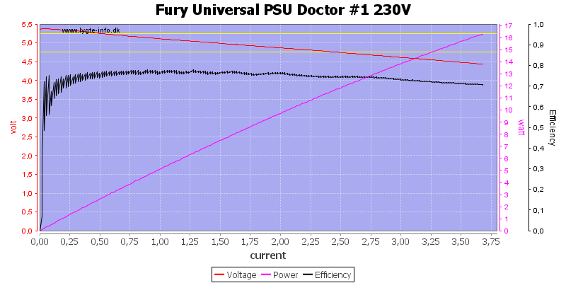
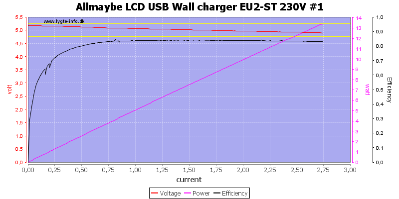
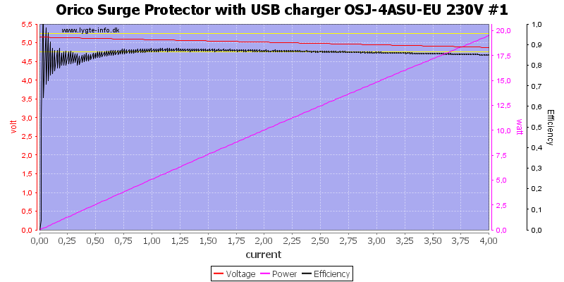
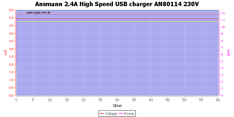
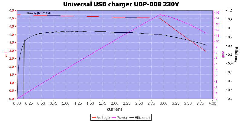
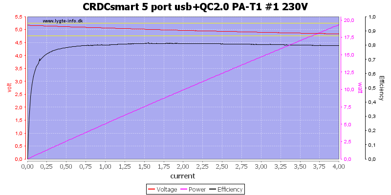
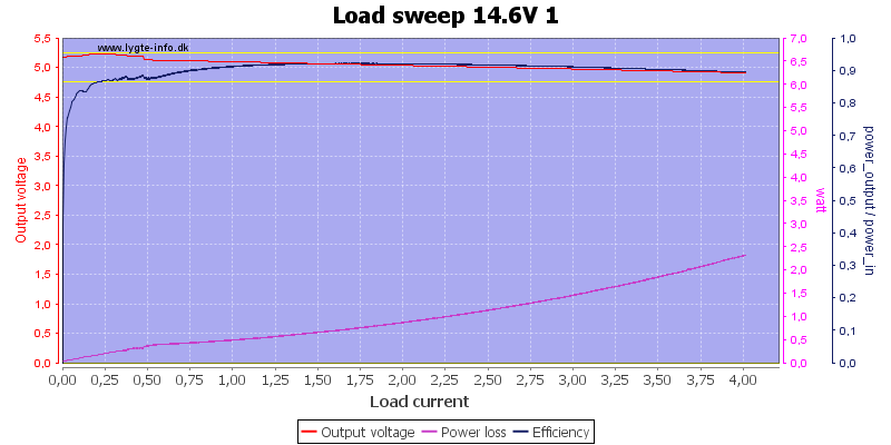
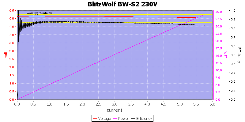
![Fury%20Universal%20PSU%20Doctor%20%231%20230V%20load%20sweep]()
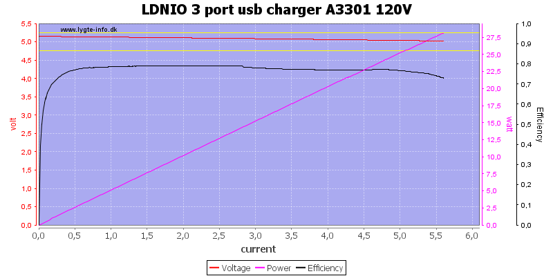
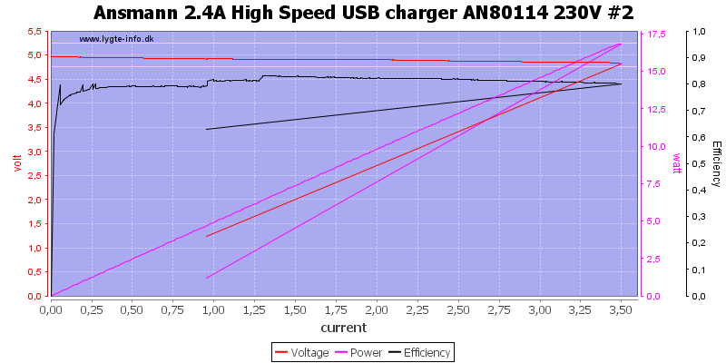
There is not much difference between 120VAC and 230VAC supply.
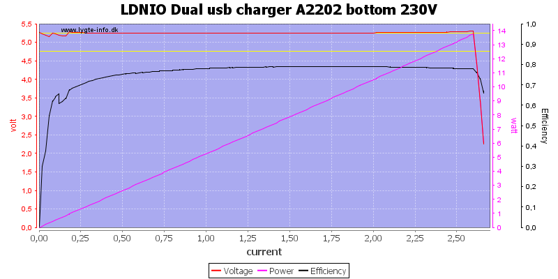
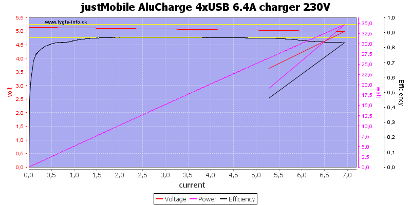
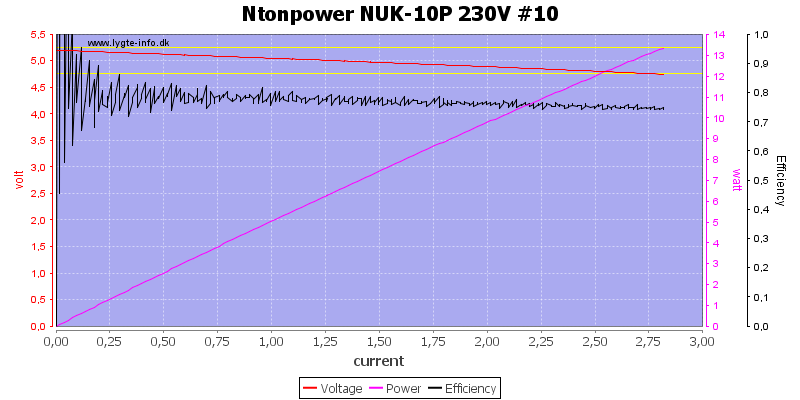
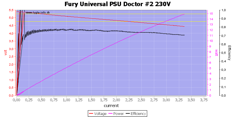
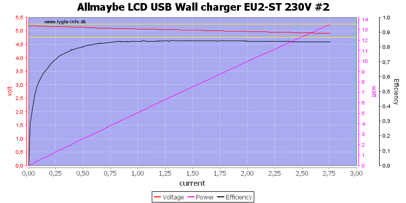
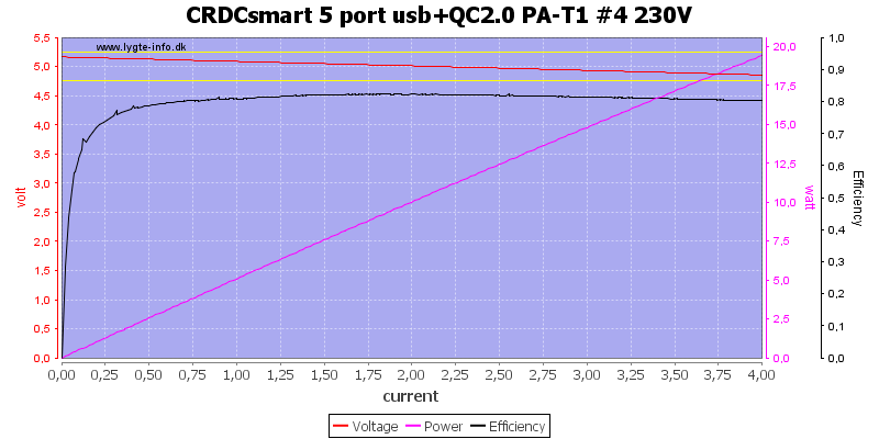
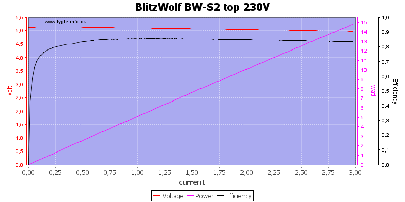
![Fury%20Universal%20PSU%20Doctor%20%232%20230V%20load%20sweep]()
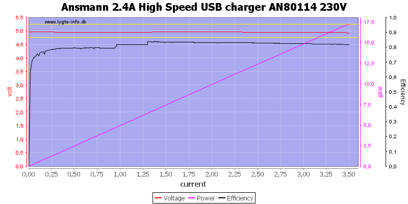
The current limit on output #2 is at about 3.2A, I do not know why it turned the output off twice at the start.
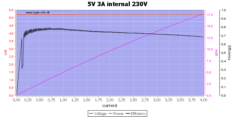
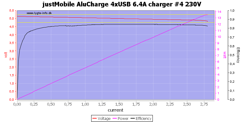
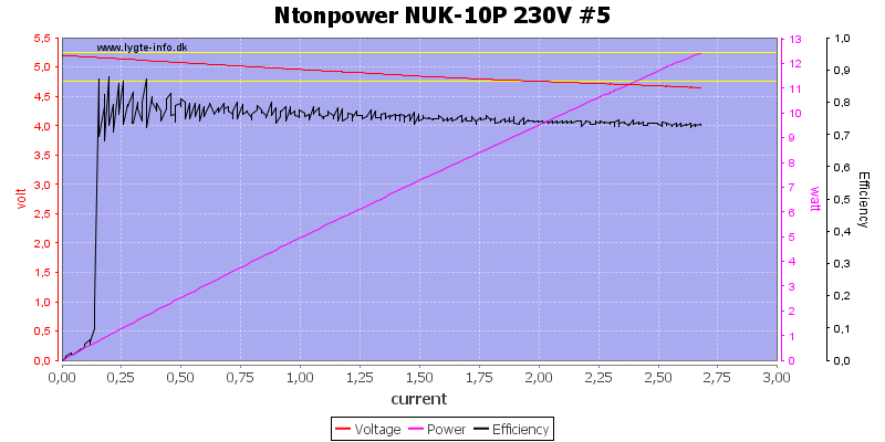
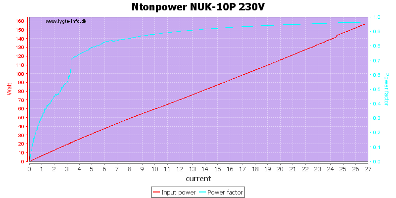
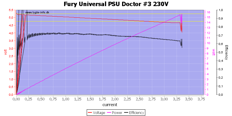
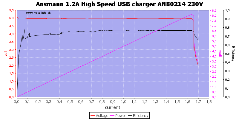
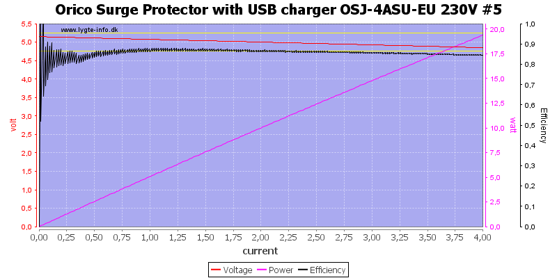
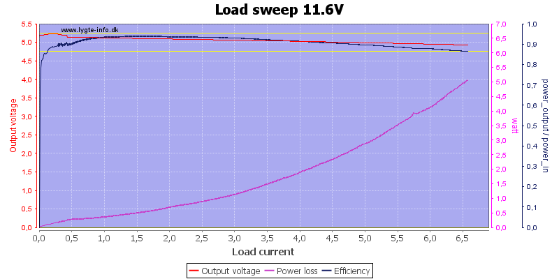
![Fury%20Universal%20PSU%20Doctor%20%233%20230V%20load%20sweep]()
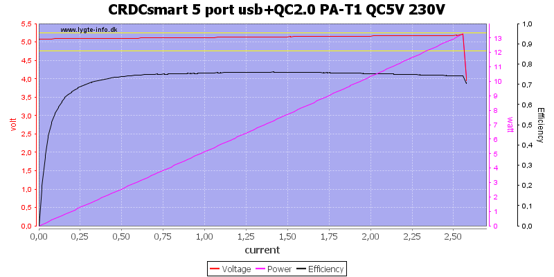
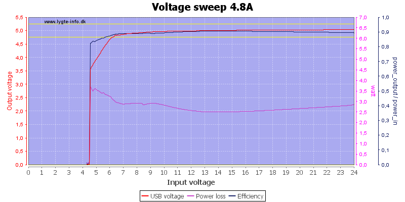
Same with output #3 when run at 5V.
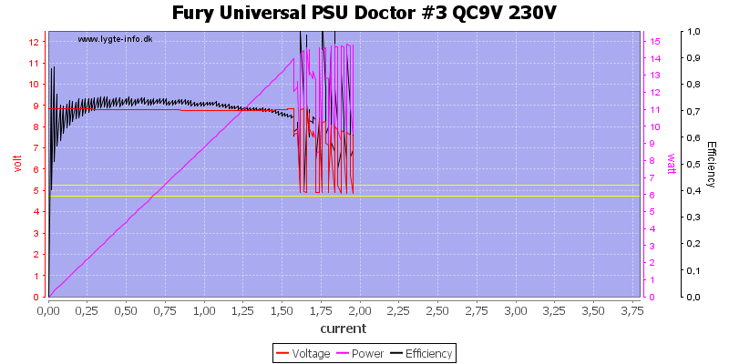
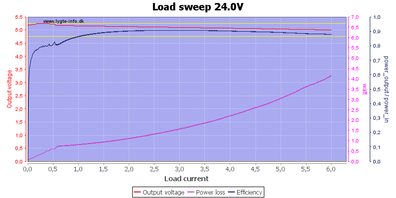
![Fury%20Universal%20PSU%20Doctor%20%233%20QC9V%20230V%20load%20sweep]()
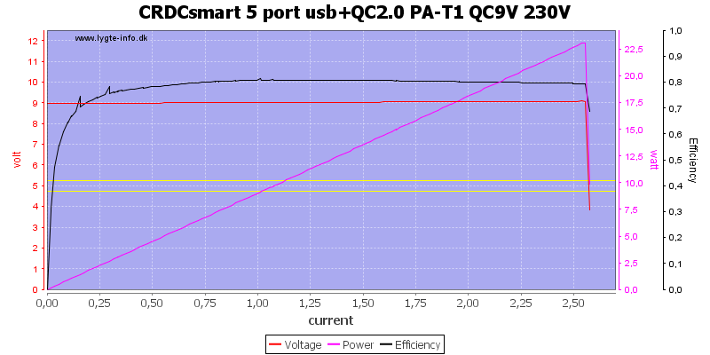
With QC at 9V the output is only about 1.6A
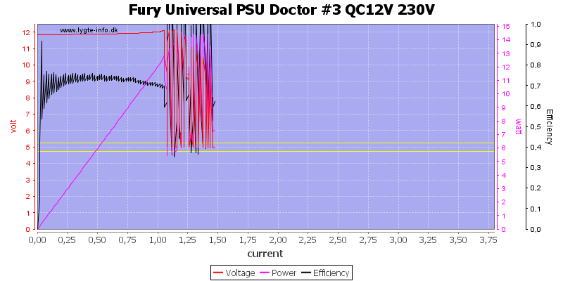
![Fury%20Universal%20PSU%20Doctor%20%233%20QC12V%20230V%20load%20sweep]()
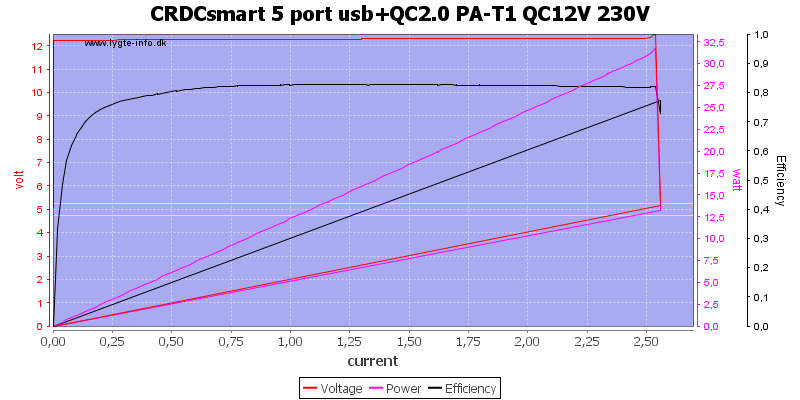
And down to about 1A at 12V.
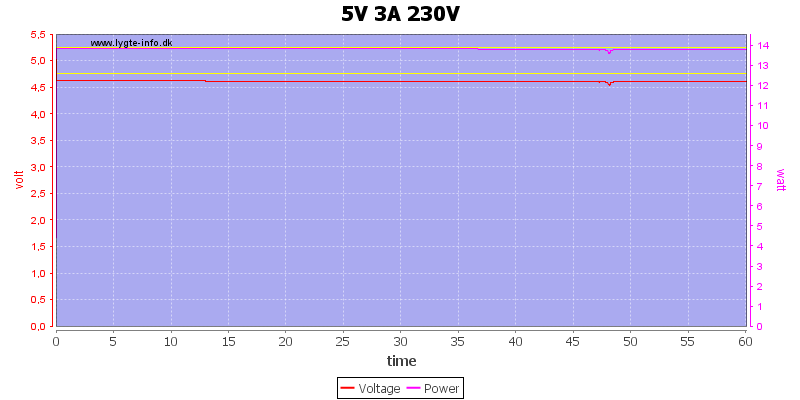
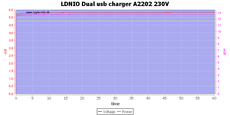
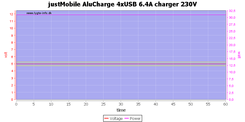
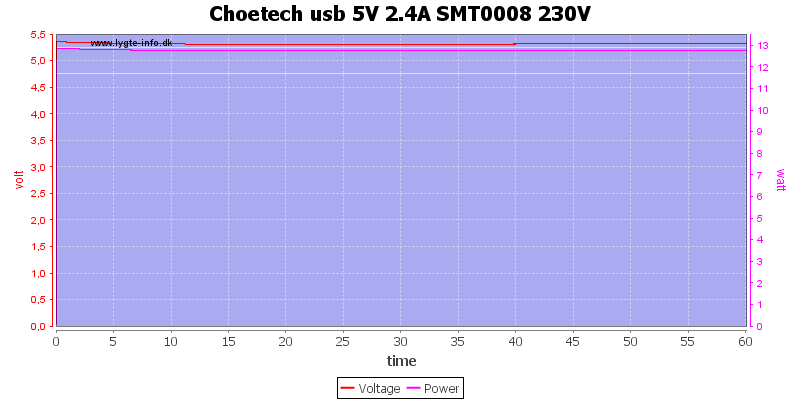
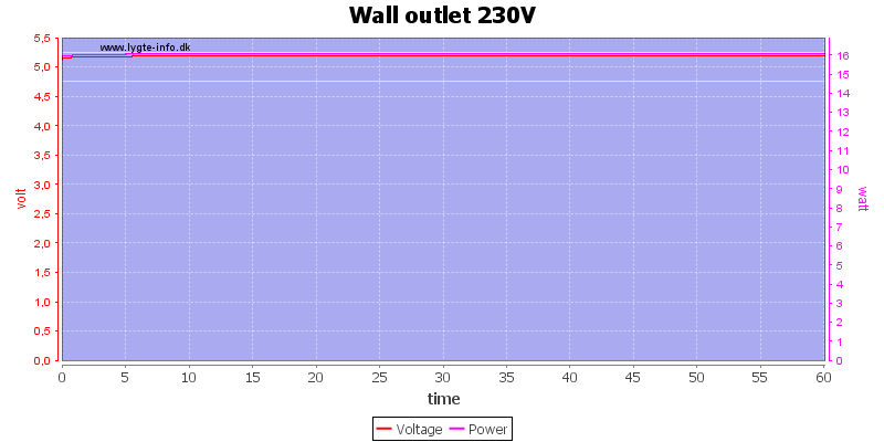
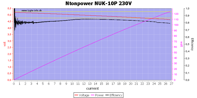
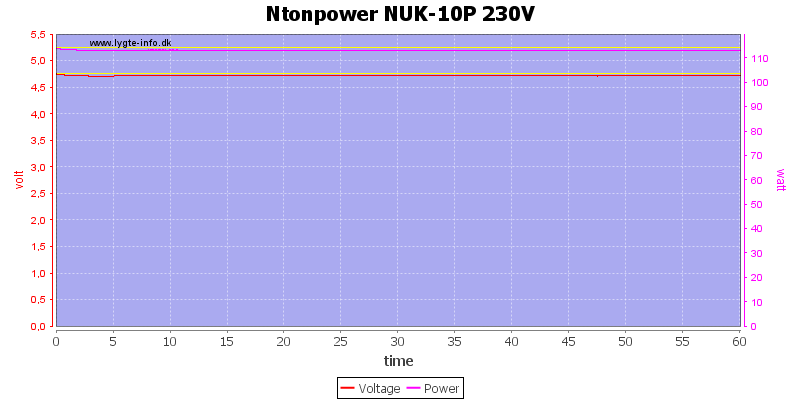
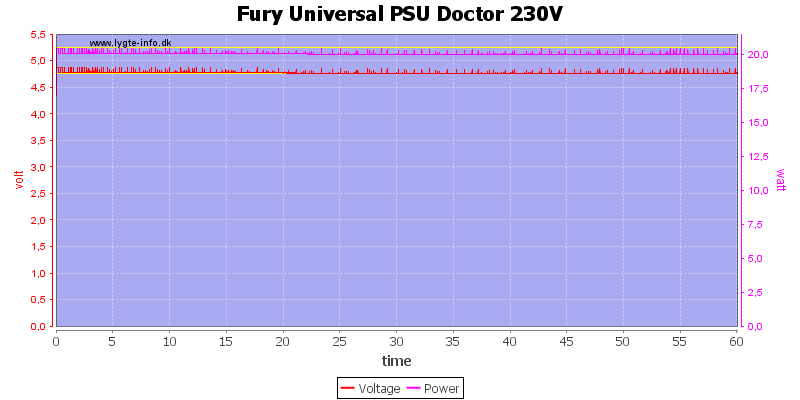
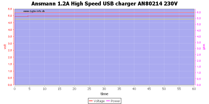
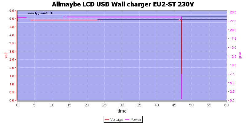
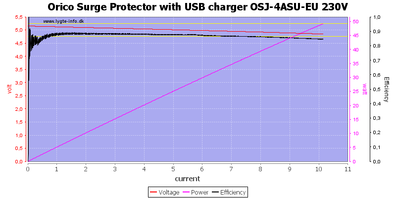
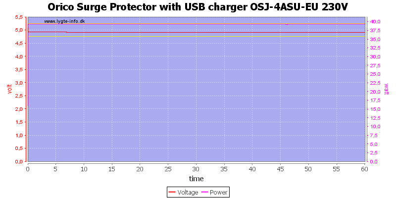
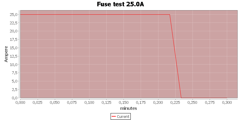
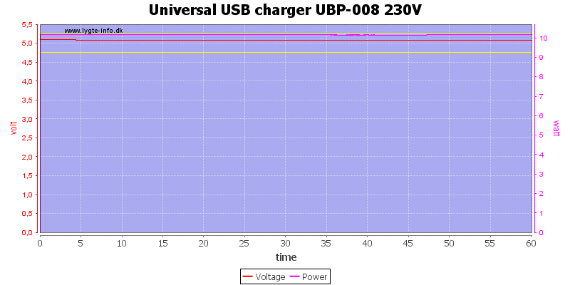
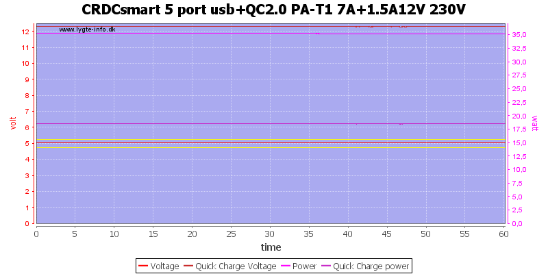
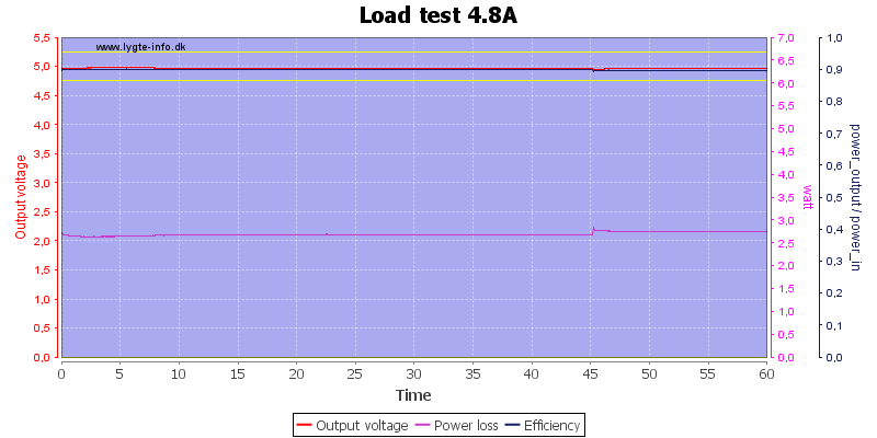
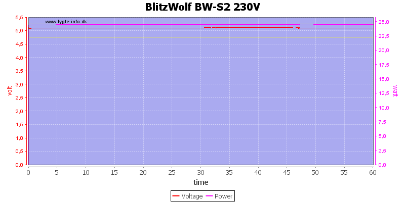
![Fury%20Universal%20PSU%20Doctor%20230V%20load%20test]()
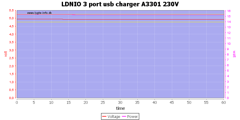
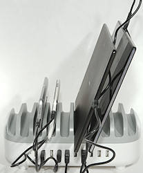
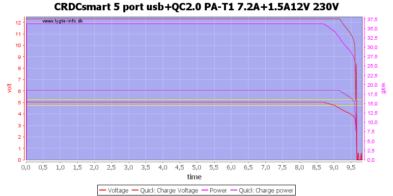
No problems running one hour at 4.2A distributed on all 3 outputs.
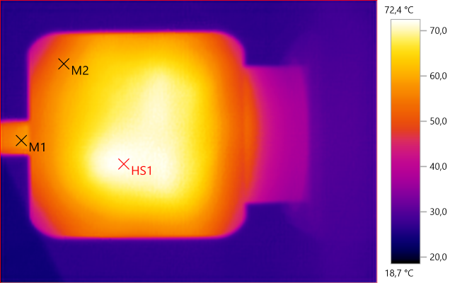
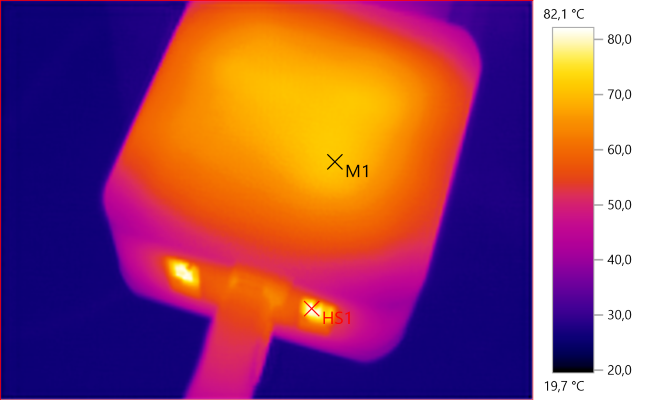
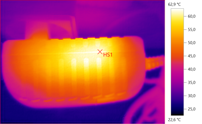
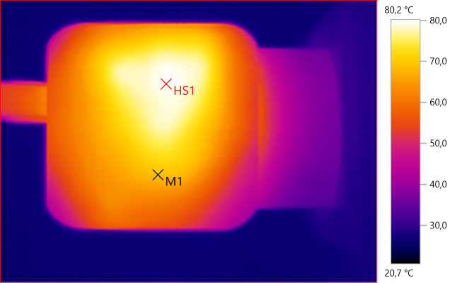
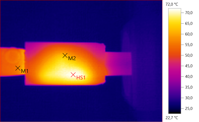
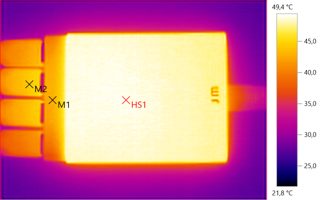
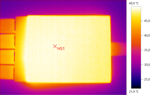
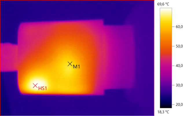
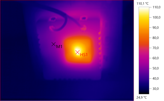
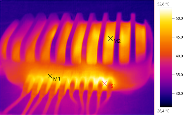
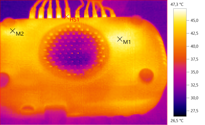
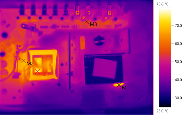
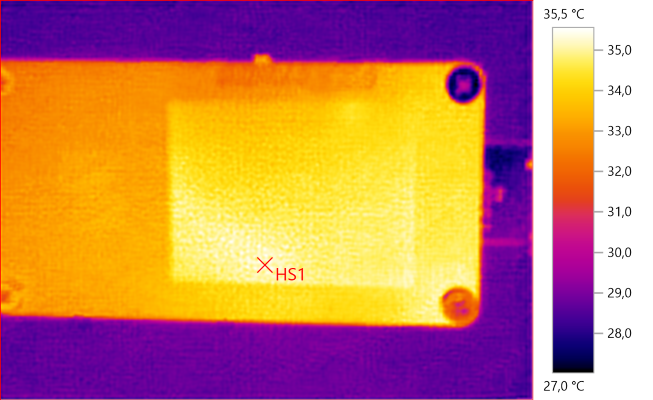
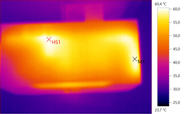
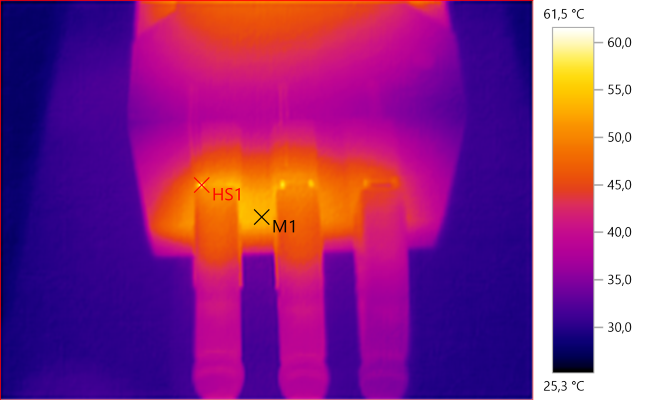
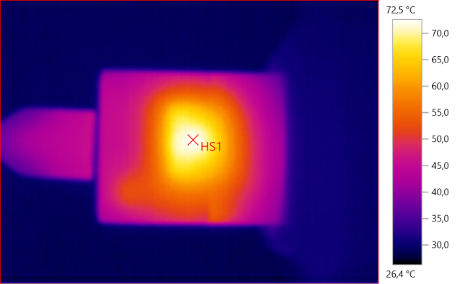
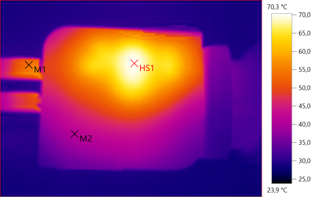
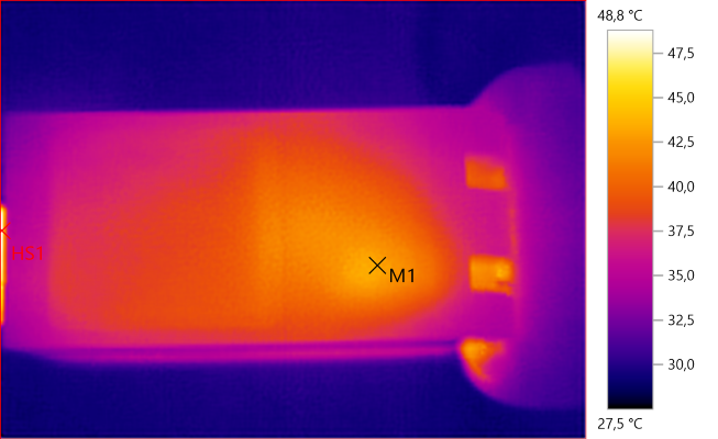
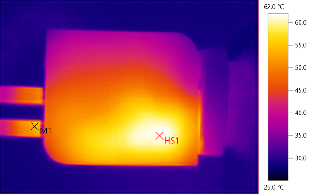
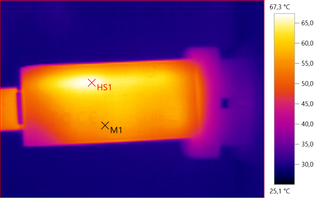
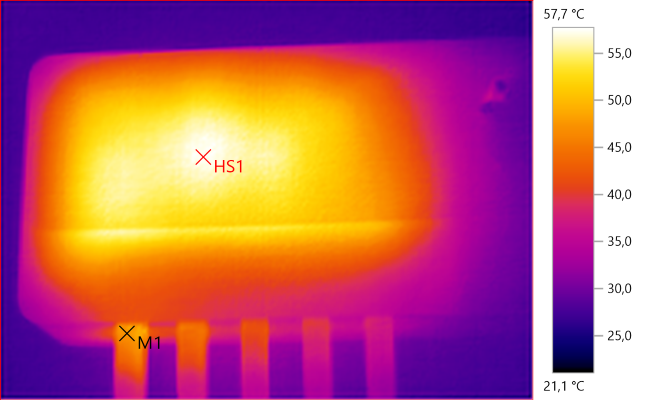
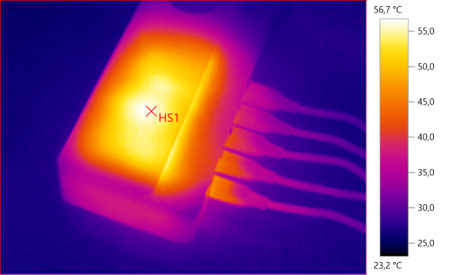
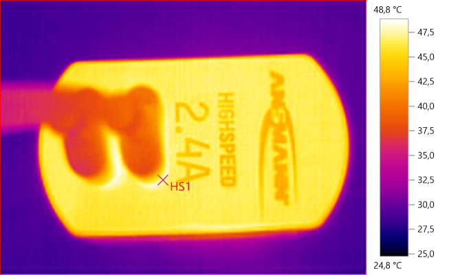
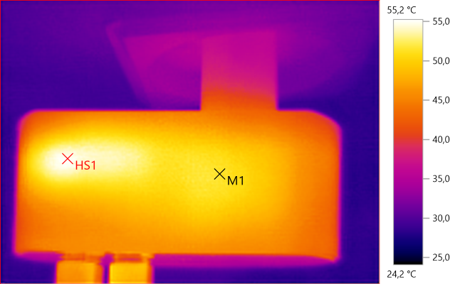
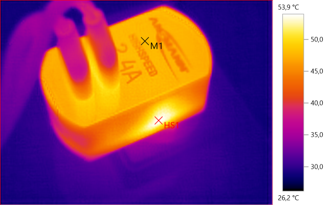
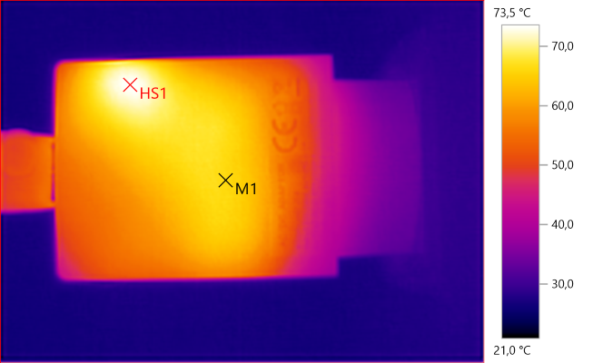
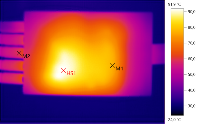
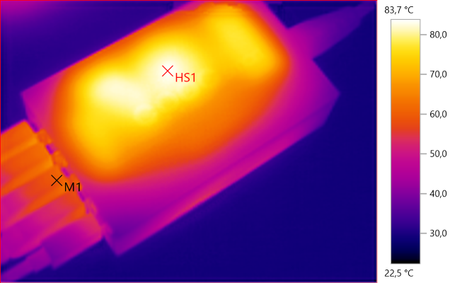
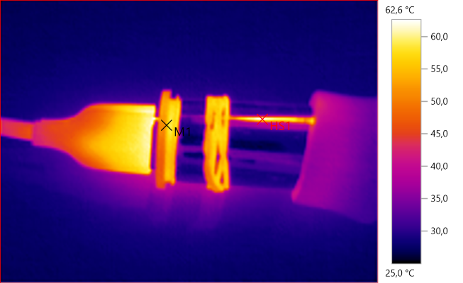
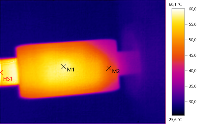
The temperature photos below are taken between 30 minutes and 60 minutes into the one hour test.
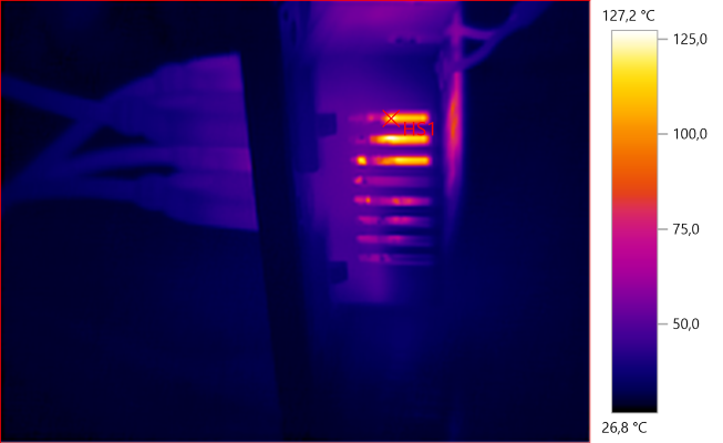
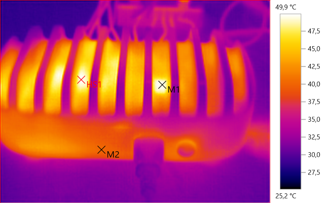
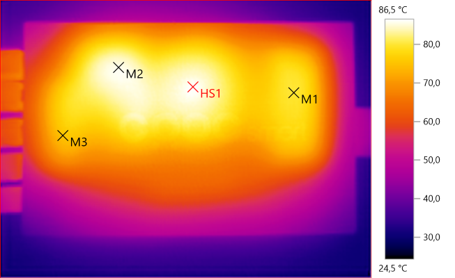
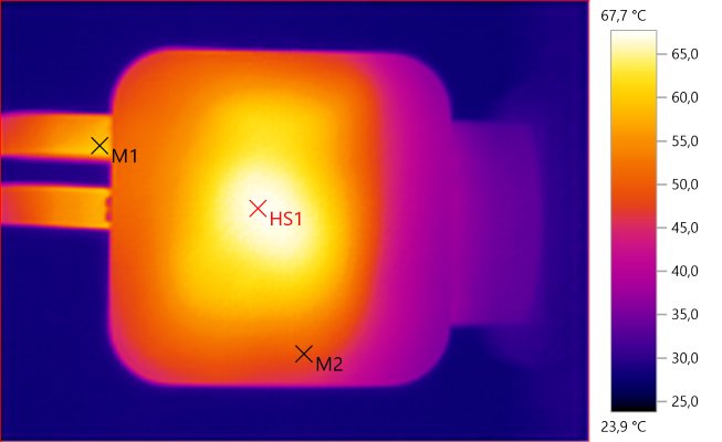
![Temp4241]()
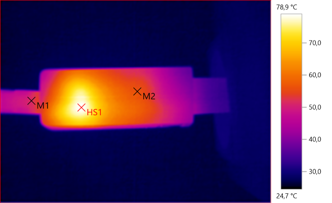
M1: 59,6°C, HS1: 60,4°C
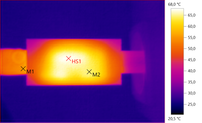
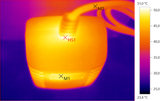
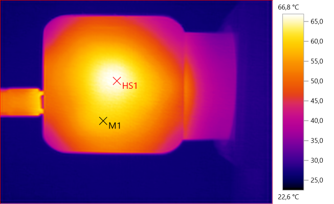
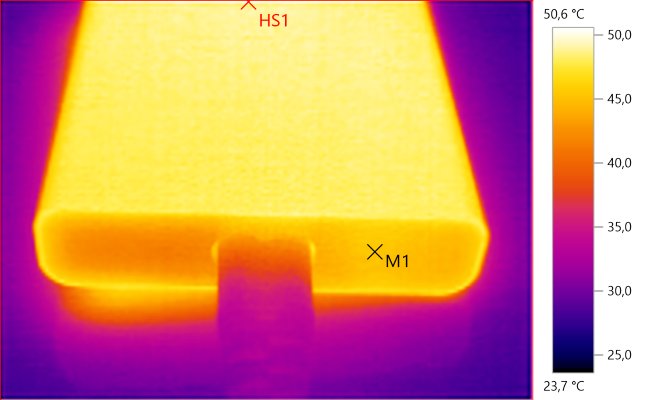
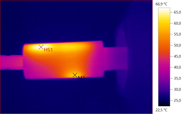
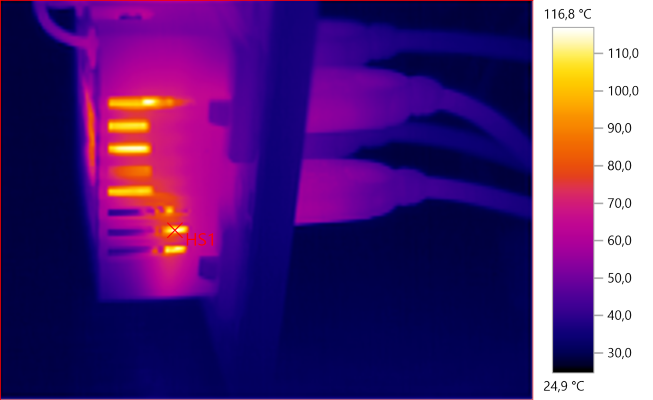
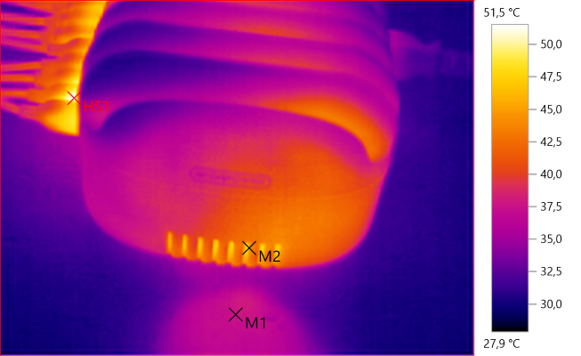
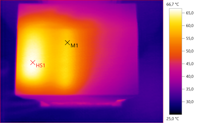
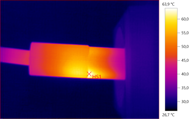
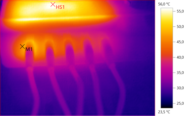
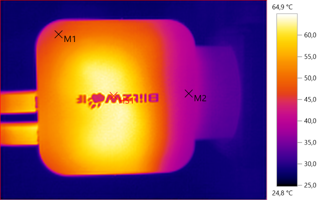
![Temp4242]()
M1: 59,5°C, HS1: 66,7°C
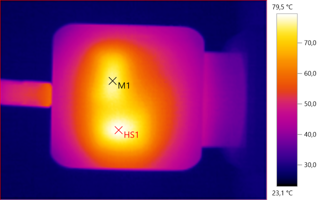
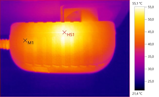
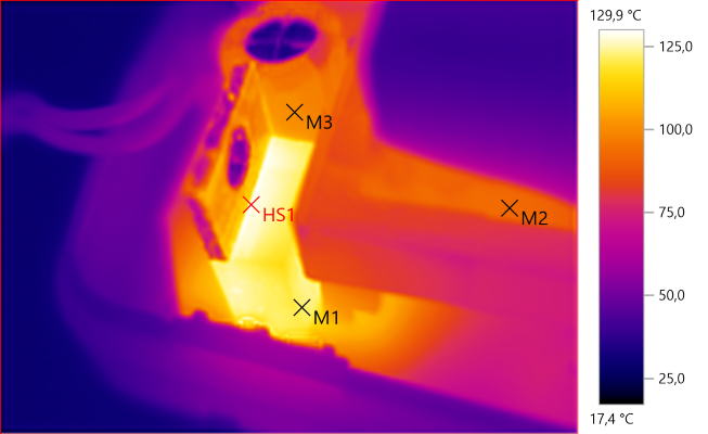
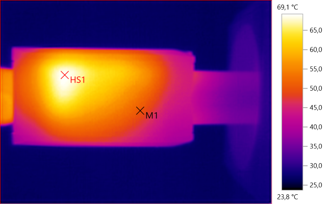
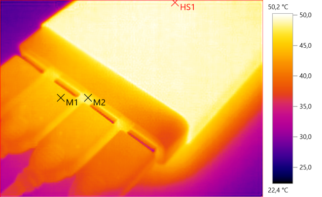
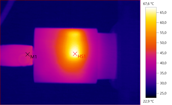
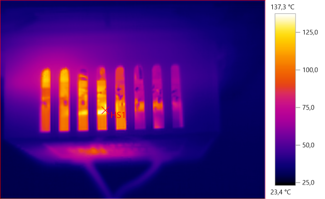
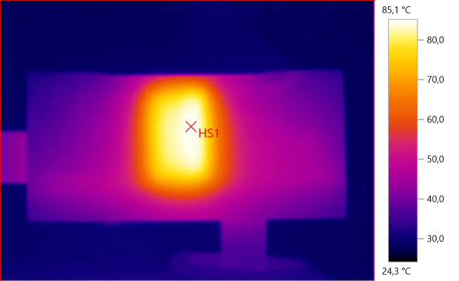
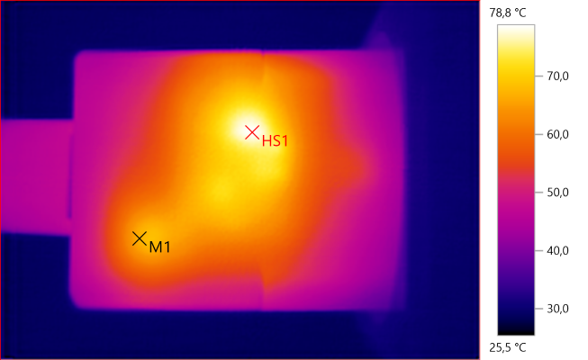
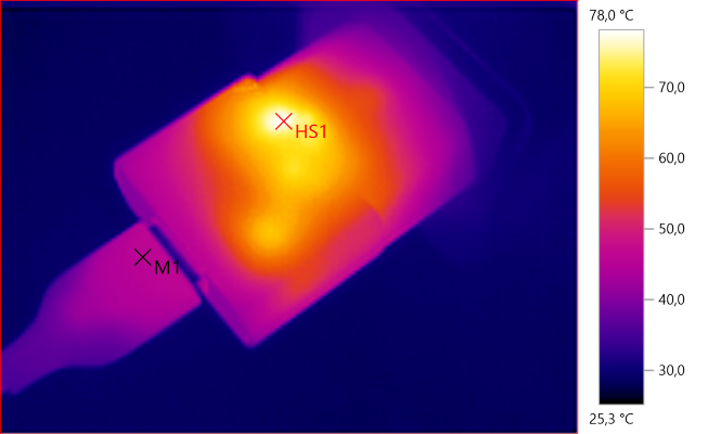
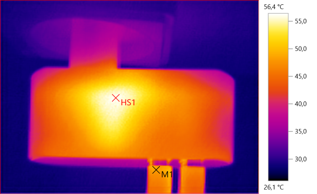
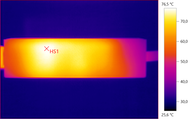
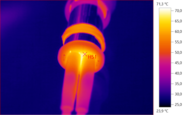
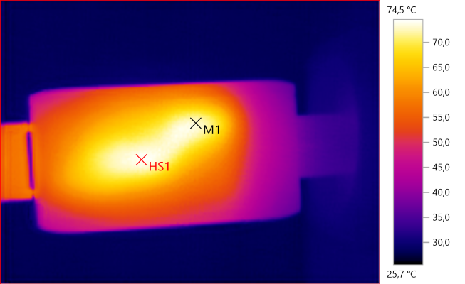
![Temp4243]()
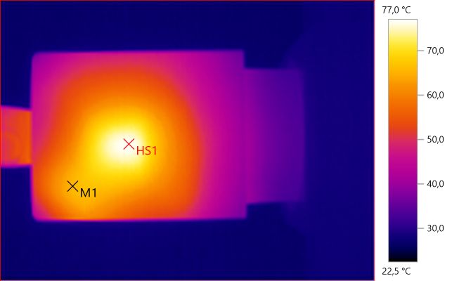
HS1: 85,1°C
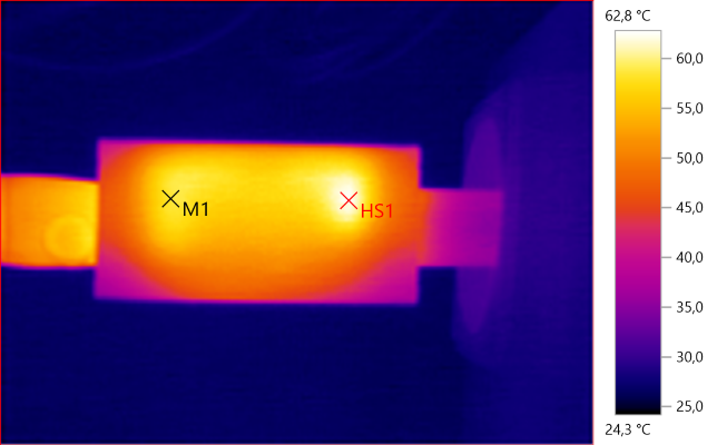
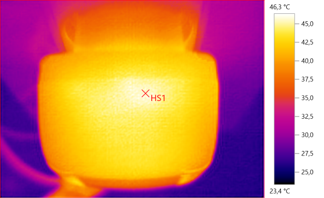
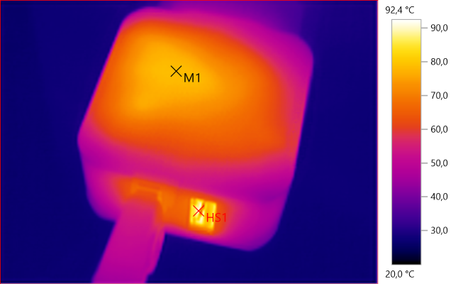
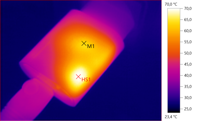
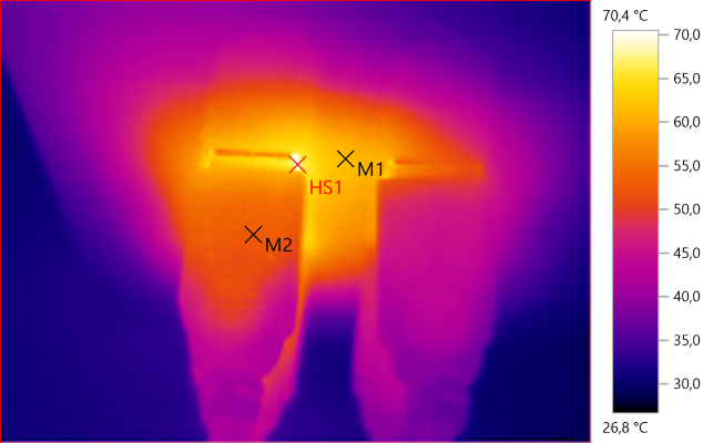
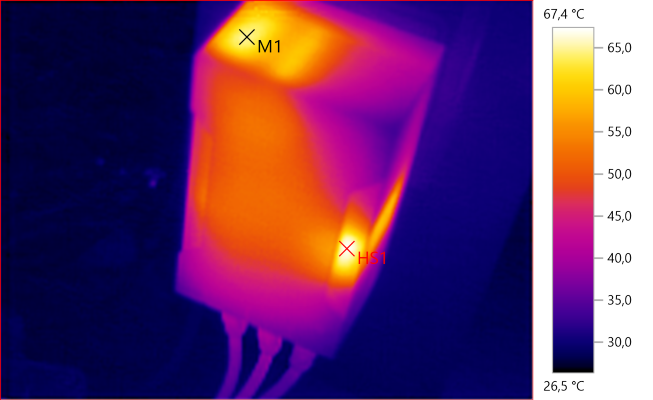
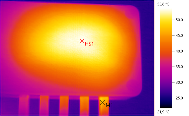
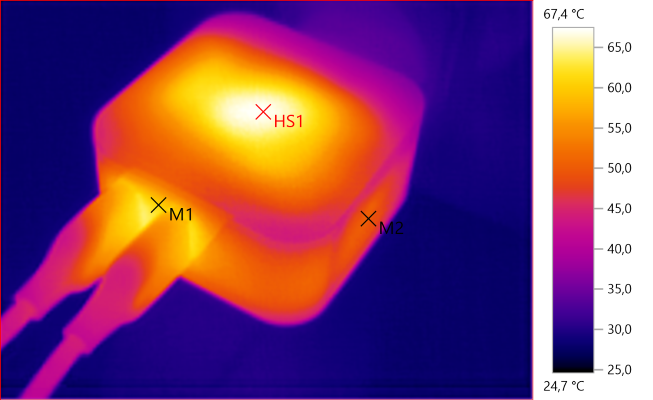
![Temp4244]()
M1: 64,6°C, HS1: 67,4°C
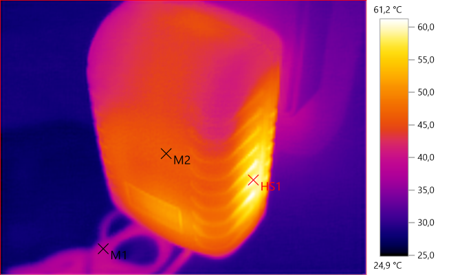
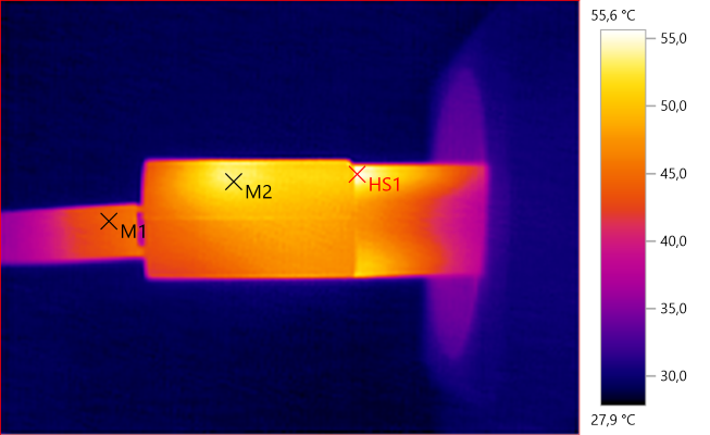
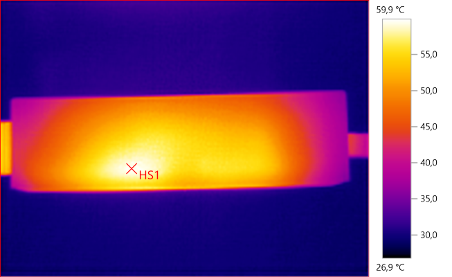
![Temp4245]()
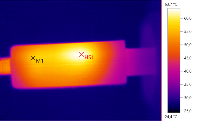
M1: 53,5°C, HS1: 61,5°C
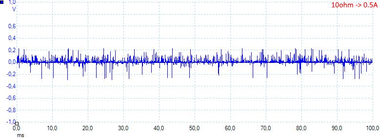
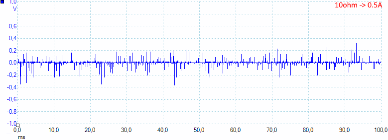
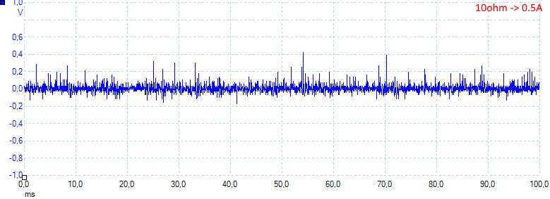
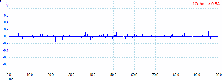
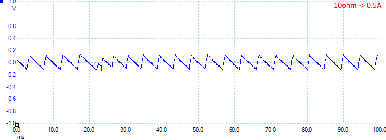
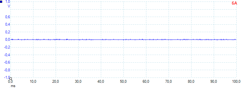
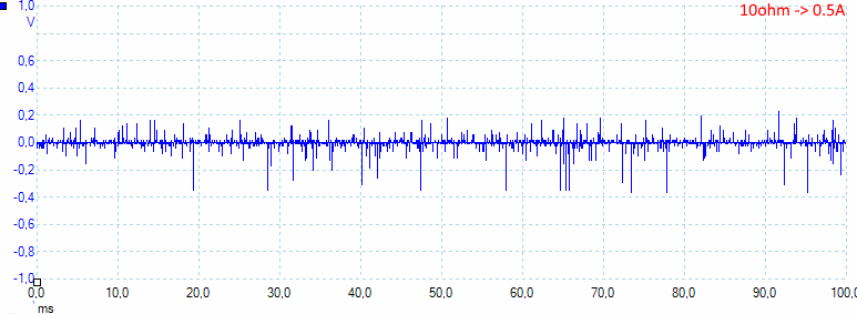
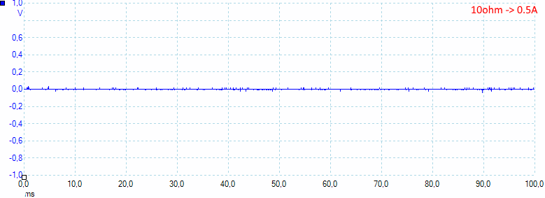
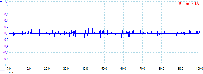
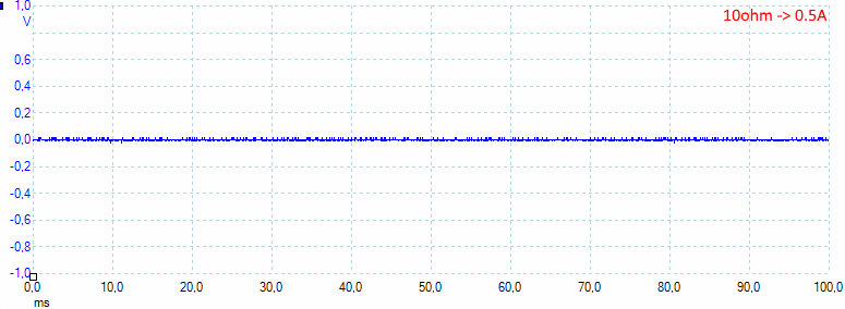
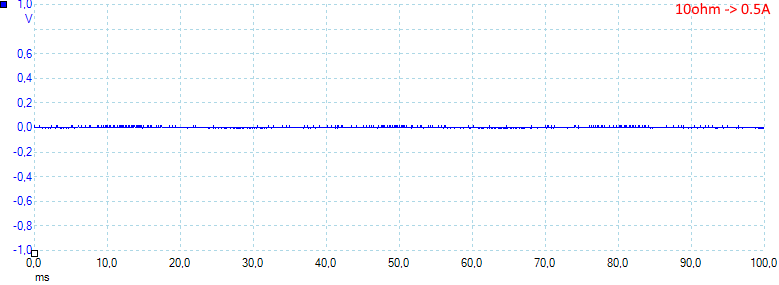
![10ohm]()
At 1A the noise is 29mV rms and 834mVpp.
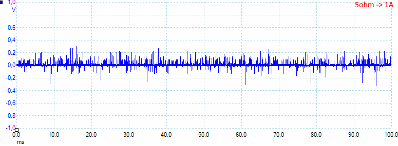
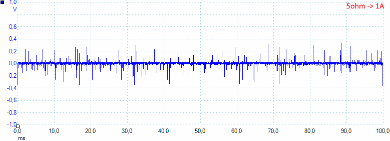
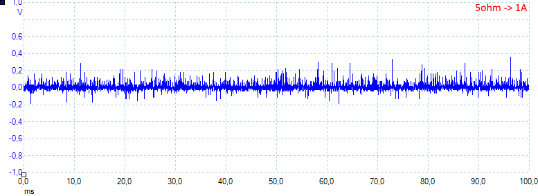
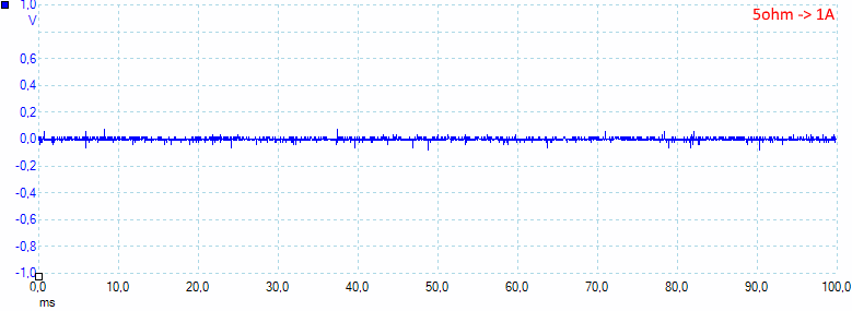
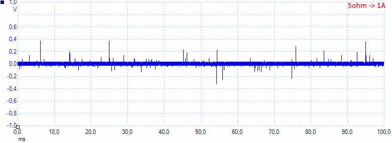
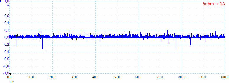
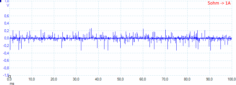
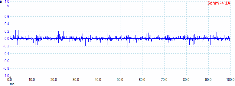
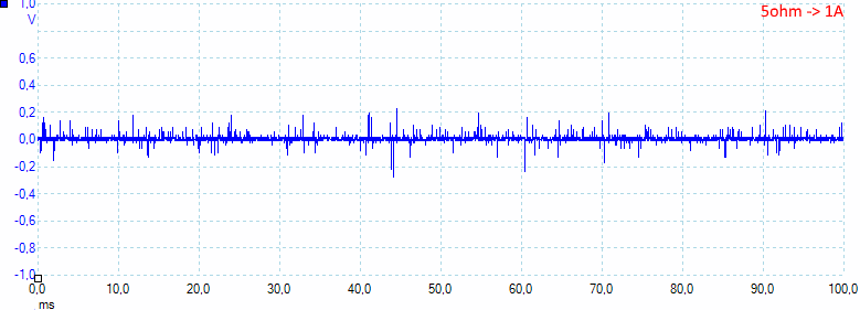
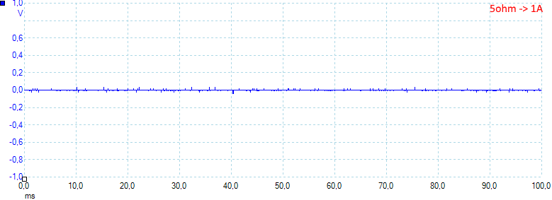
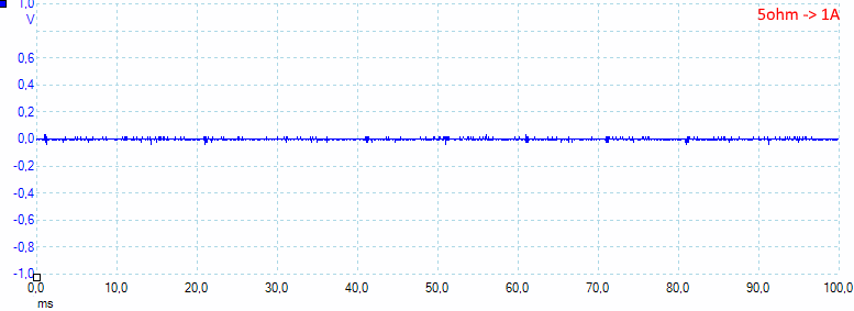
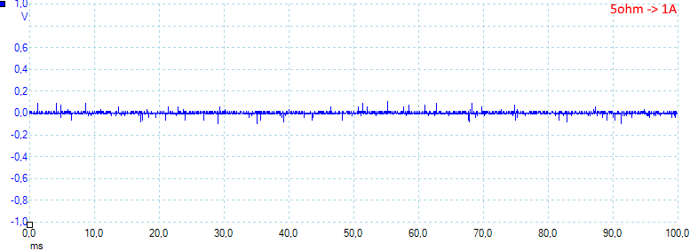
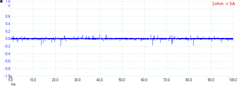
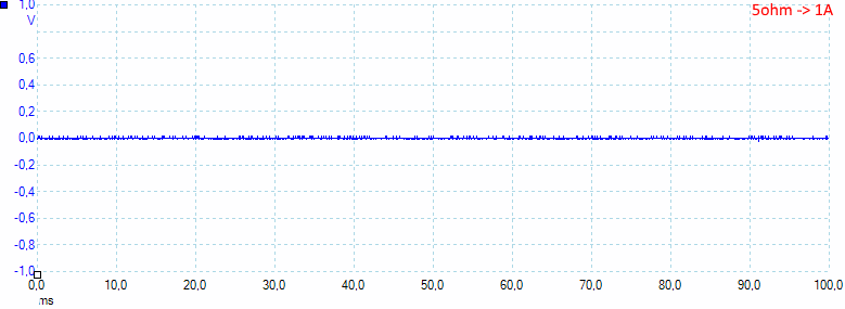
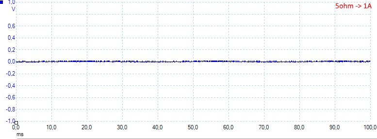
![5ohm]()
At 1A the noise is 29mV rms and 763mVpp.
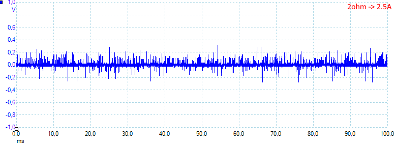
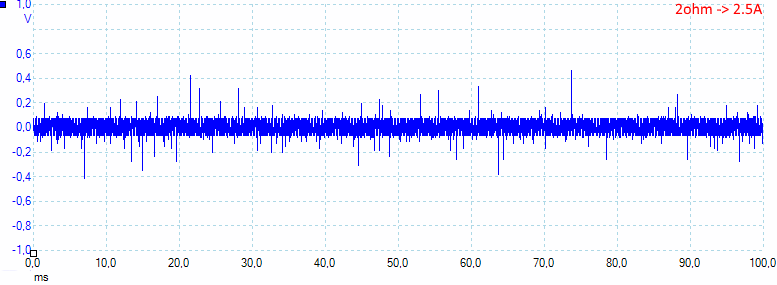
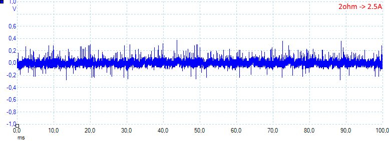
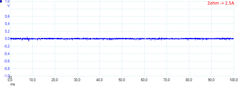
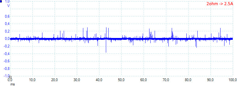
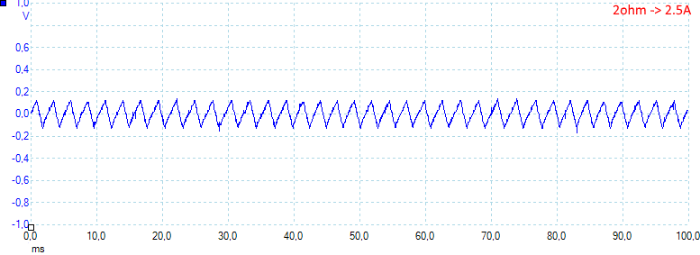
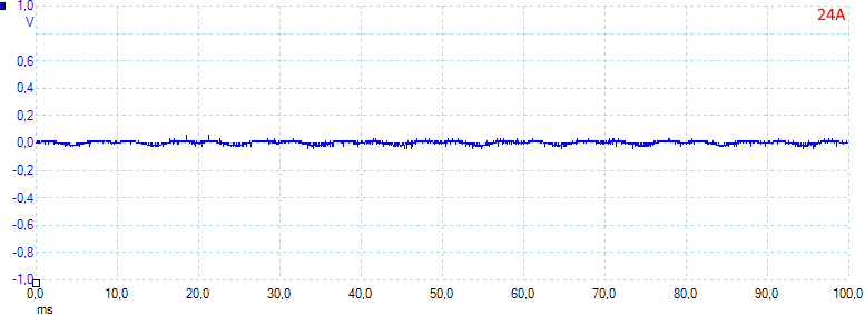
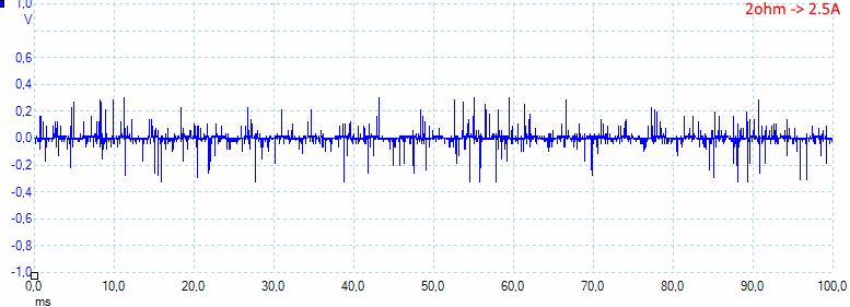
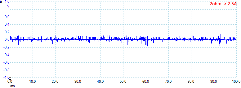
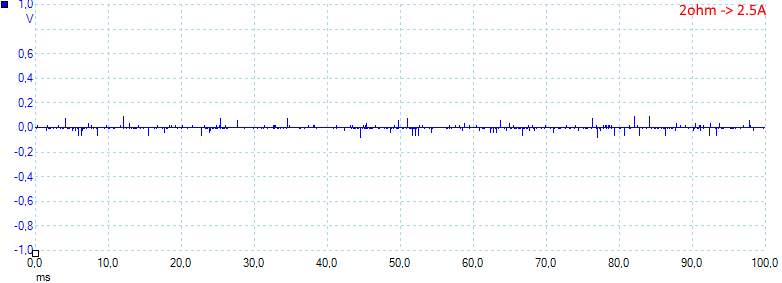
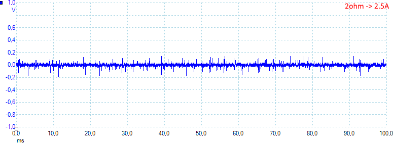
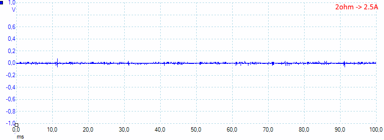
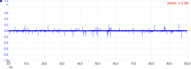
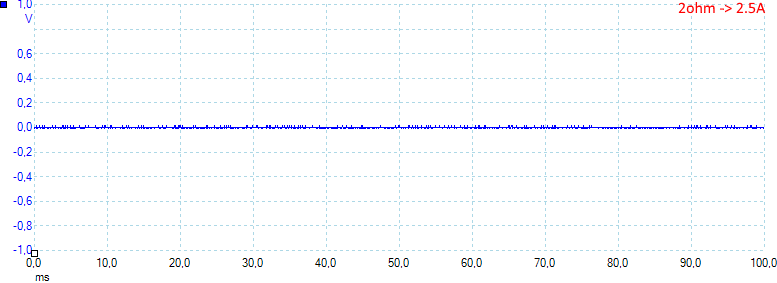
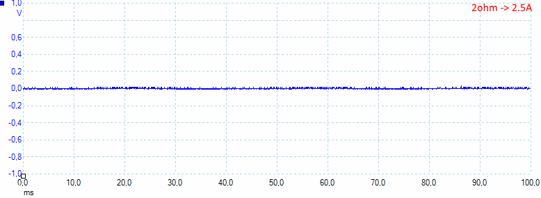
![2ohm]()
At 2.5A the noise is 35mV rms and 790mVpp.
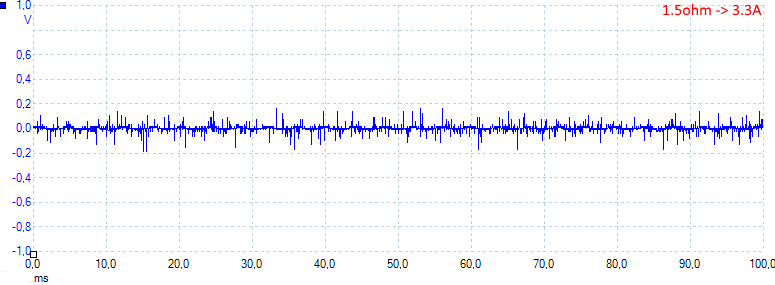
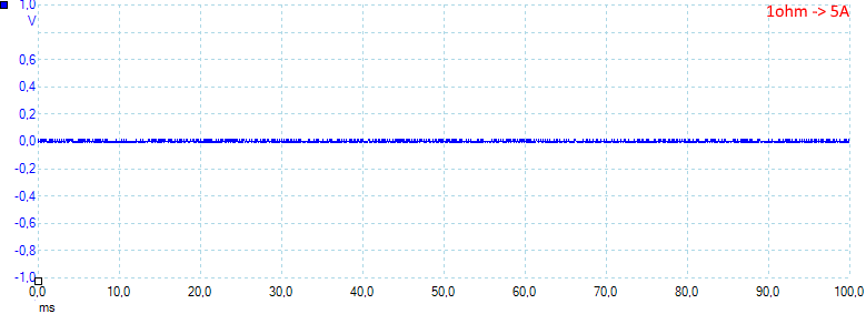
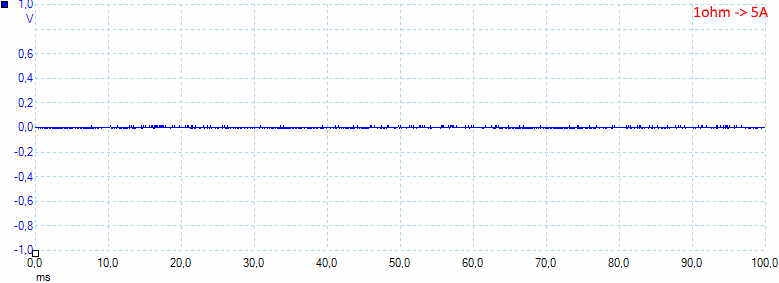
![1.5ohm]()
At 3.3A the noise is 222mV rms and 485mVpp.
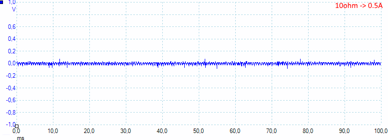
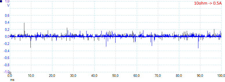
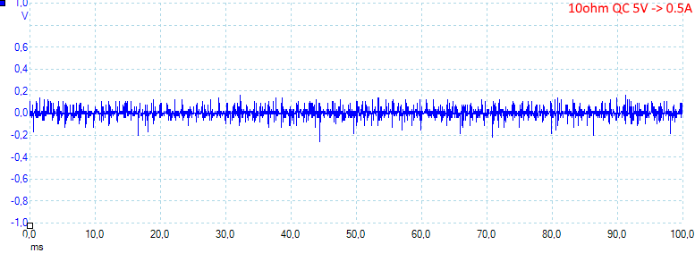
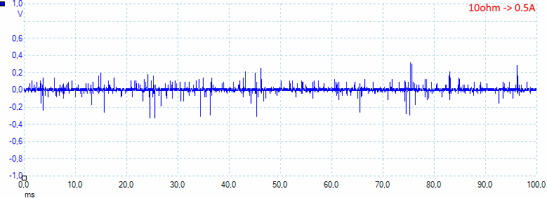
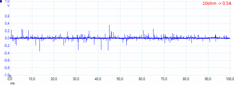
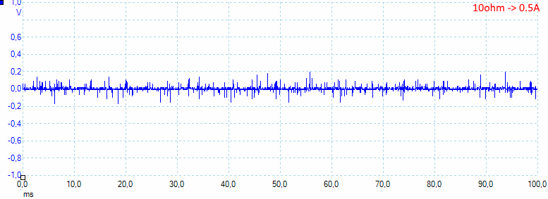
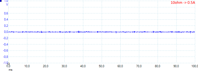
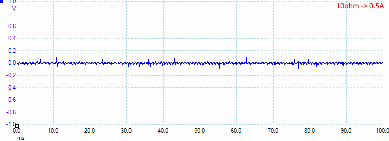
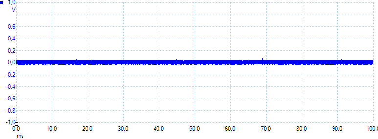
![10ohmQC5V]()
At 0.5A the noise is 26mV rms and 666mVpp.
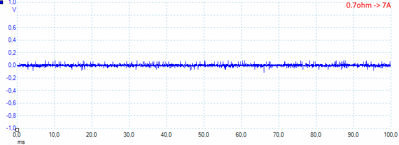
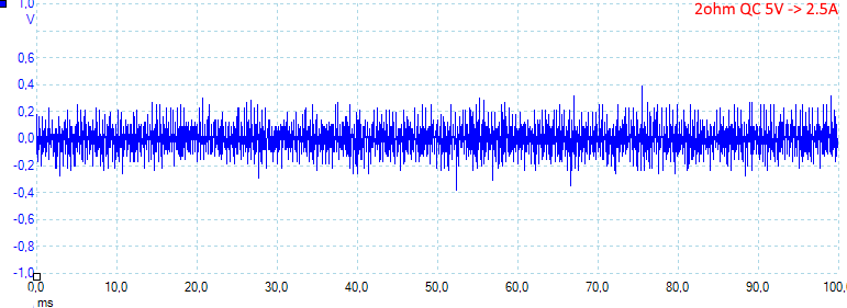
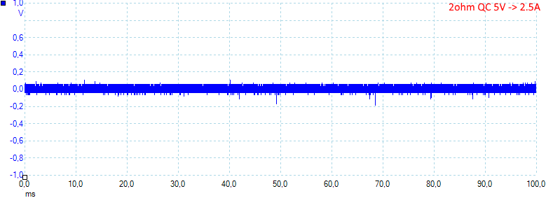
![2ohmQC5V]()
At 2.5A the noise is mV 74rms and 1059mVpp.
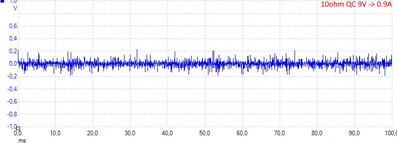
![10ohmQC9V]()
At 0.9A the noise is 37mV rms and 550mVpp.
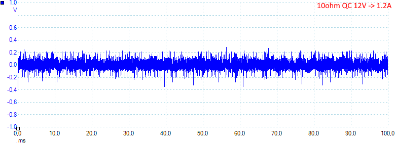
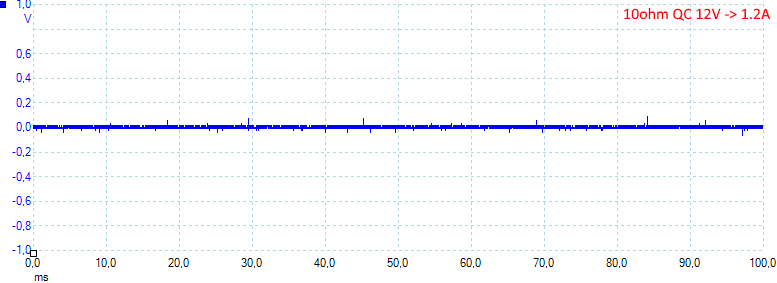
![10ohmQC12V]()
At 1.2A the noise is 80mV rms and 891mVpp.
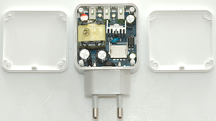
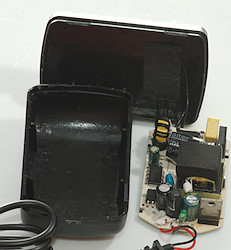
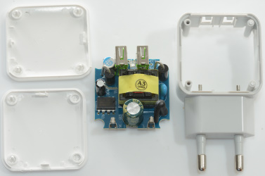
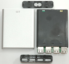
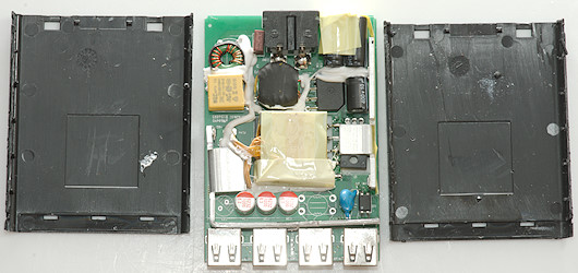
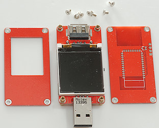
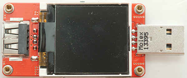
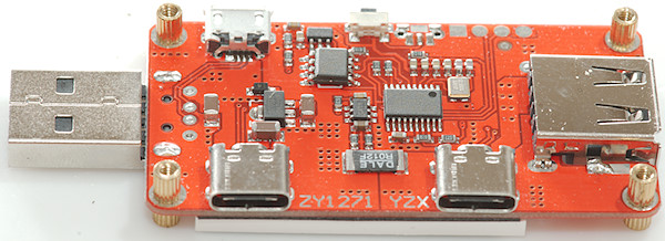
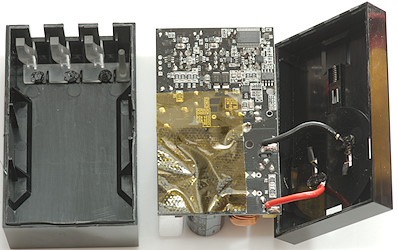
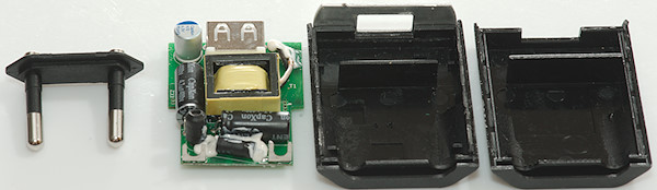
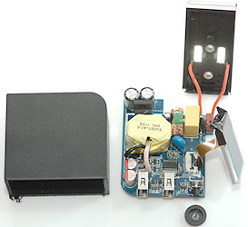
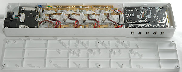
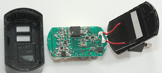
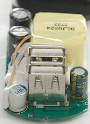
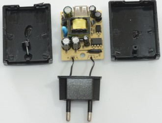
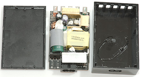
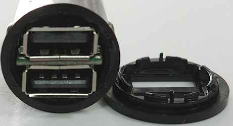
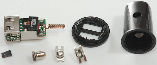
Tear down![DSC_0082]()
Some directed pressure with my vice could crack it open.
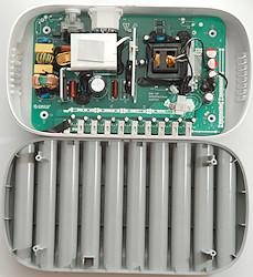
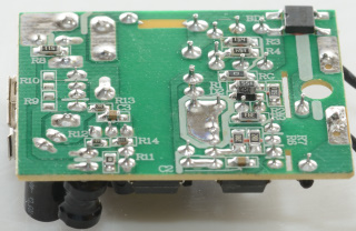
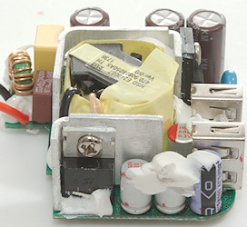
![DSC_0087]()
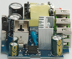
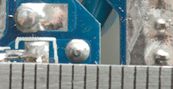
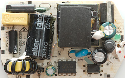
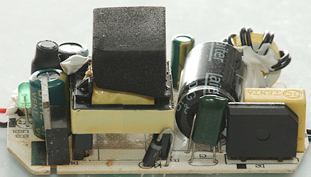
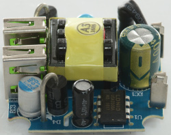
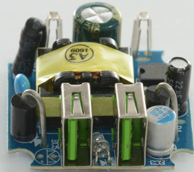
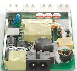
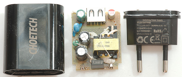
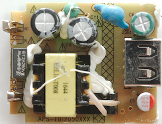
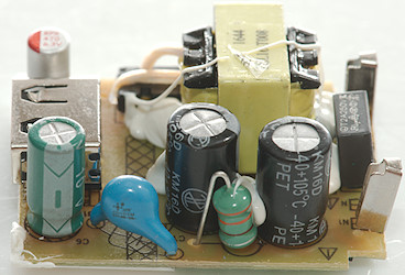
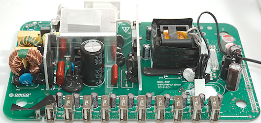
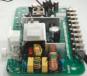
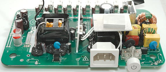
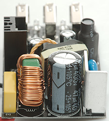
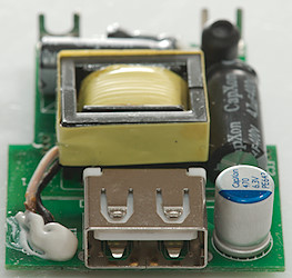
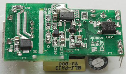
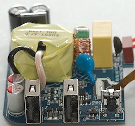
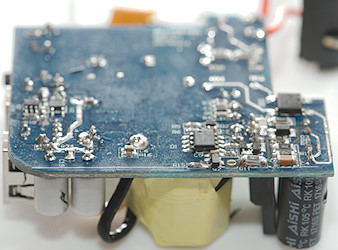
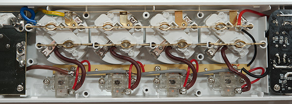
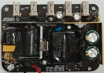
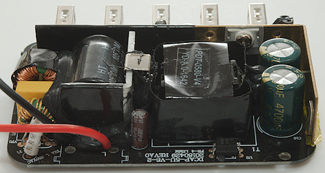
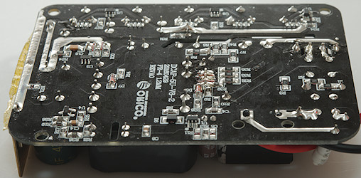
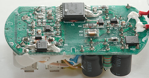
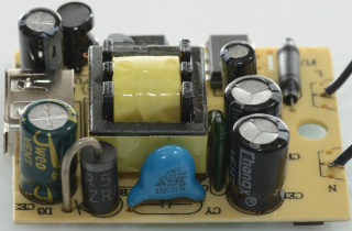
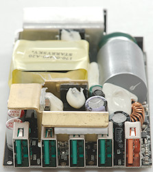
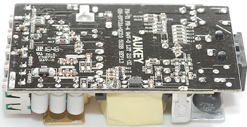
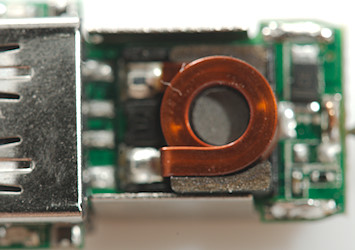
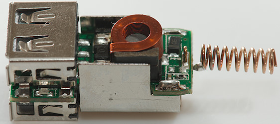
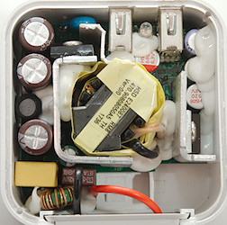
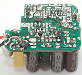
At the mains input is a fuse and a fairly large common mode coil. The switcher IC (U1: LNK6765E) is mounted on a heatsink. The safety capacitor (CY1) is mounted beside the transformer. Next to the capacitor is a filter inductor (L2) for the low voltage. The flat inductor (L3) is for the QC voltage adjustment. On the black heatsink is the rectifier diode (D1). Between the usb connectors are the indicator leds.
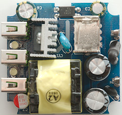
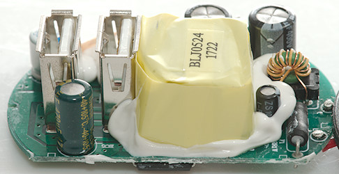
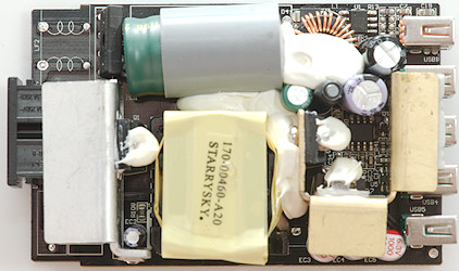
![DSC_0088]()
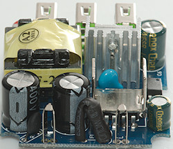
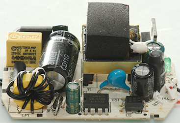
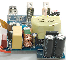
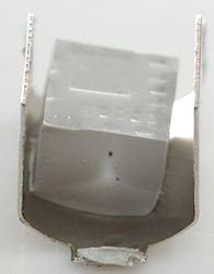
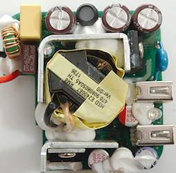
The switcher is mounted with a clamp to a heatsink. The safety capacitor has a lot of approvals (as usual).
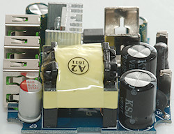
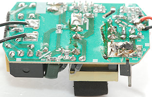
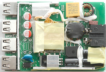
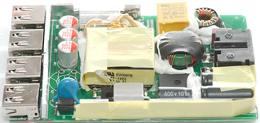
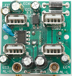
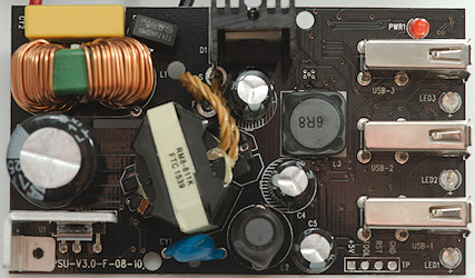
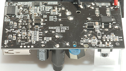
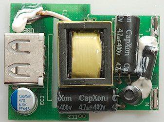
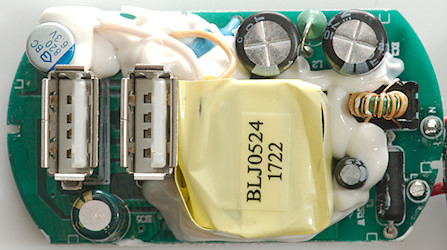
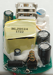
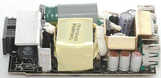
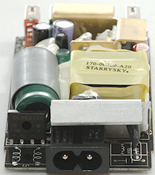
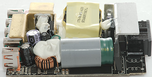
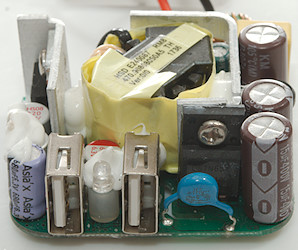
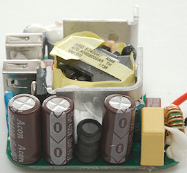
![DSC_0089]()
![DSC_0091]()
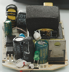
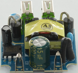
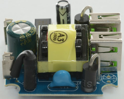
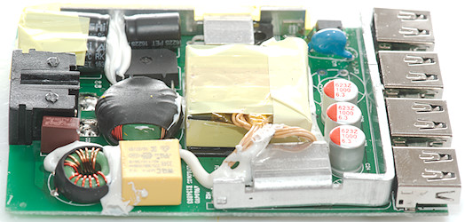
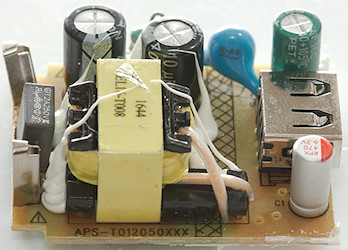
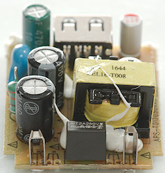
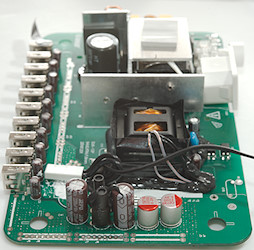
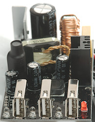
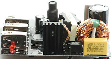
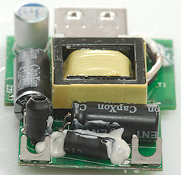
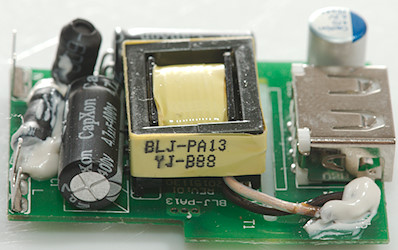
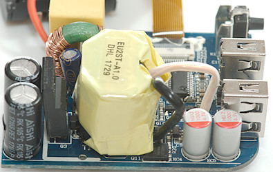
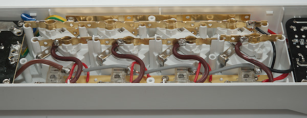
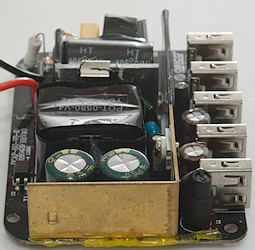
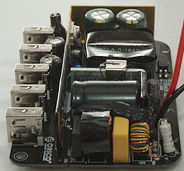
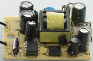
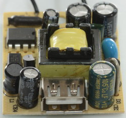
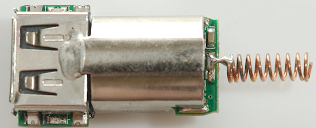
On the first picture the common mode coil is in front, on the second picture the usb connectors and the four leds (3 blue + one red) are in front.
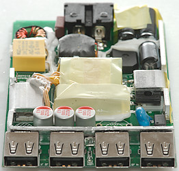
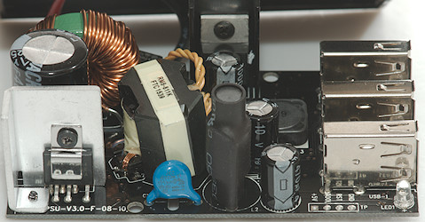
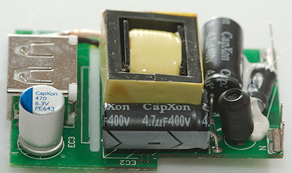
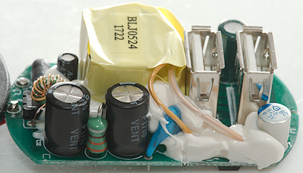
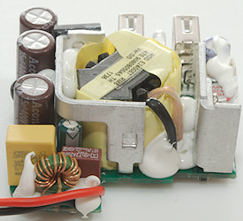
![DSC_0090]()
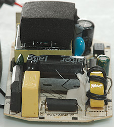
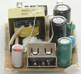
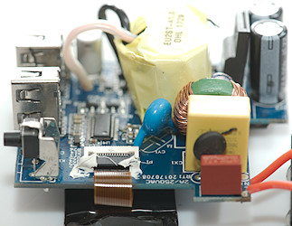
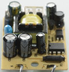
The heatsink for the rectifier diode is next to the input fuse.
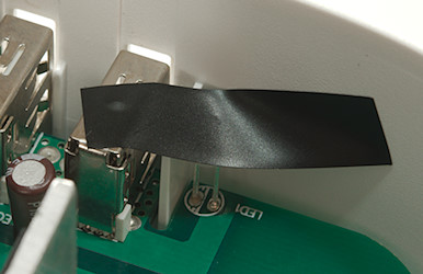
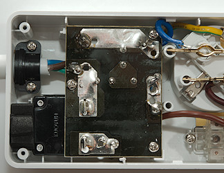
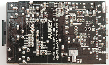
![DSC_0083]()
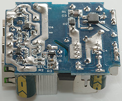
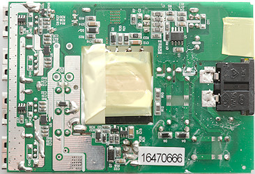
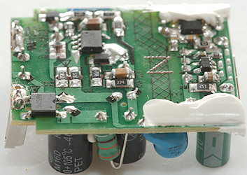
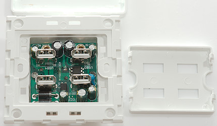
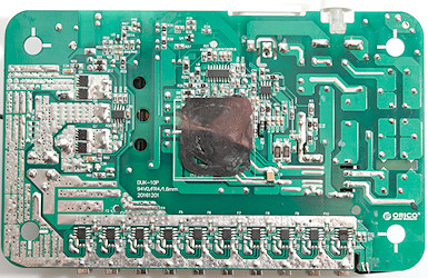
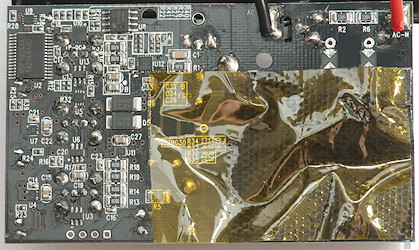
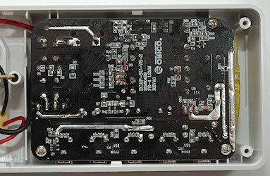
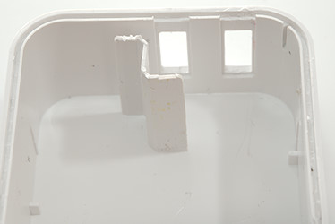
Part of this side is covered in isolation tape, that is the part above the mains input.
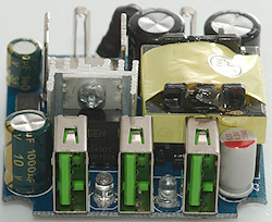
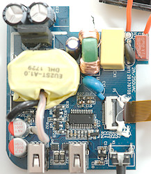
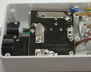
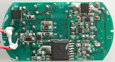
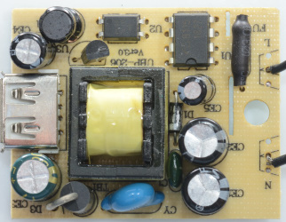
![DSC_0084]()
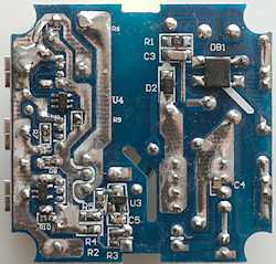
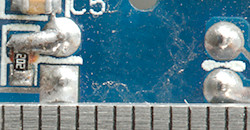
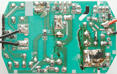
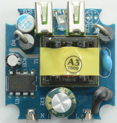
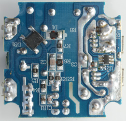
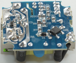
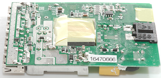
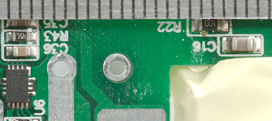
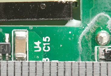
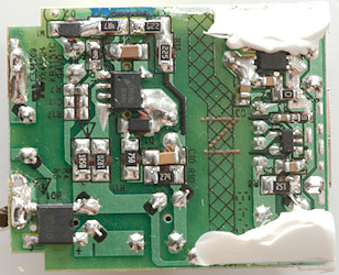
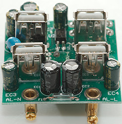
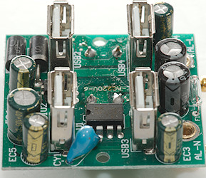
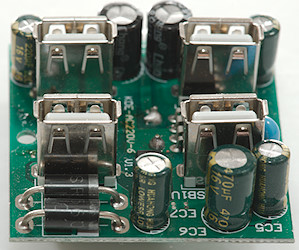
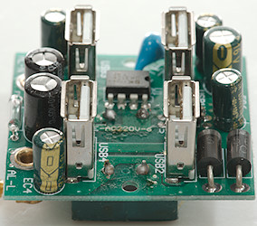
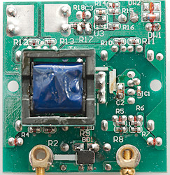
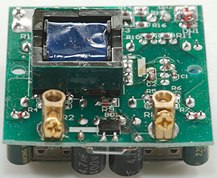
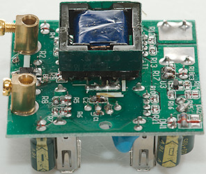
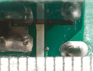
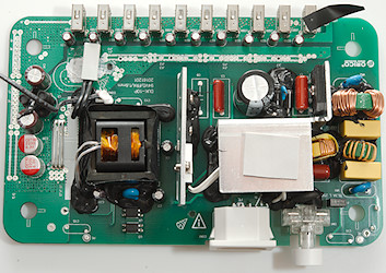
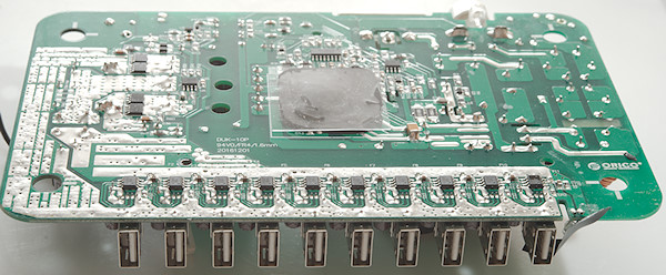
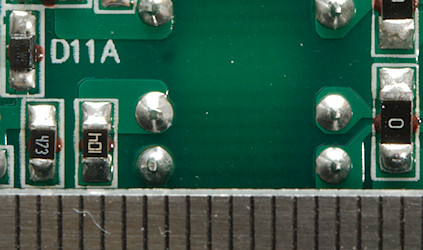
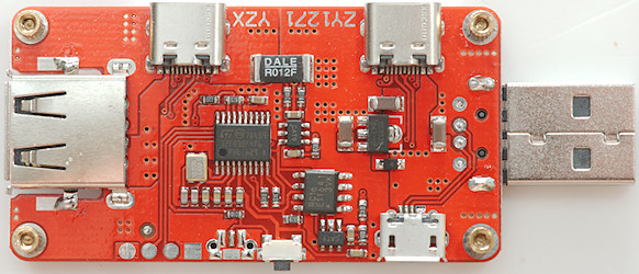
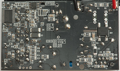
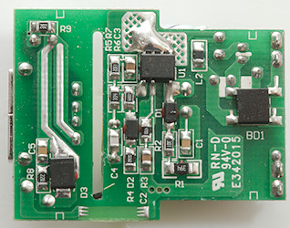
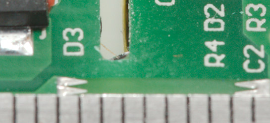
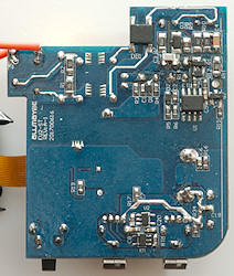
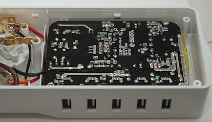
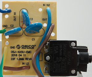
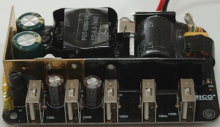
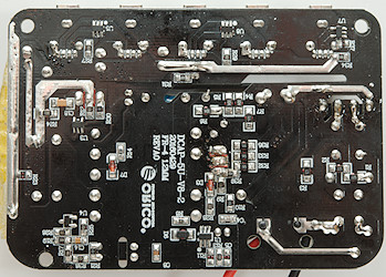
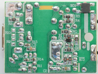
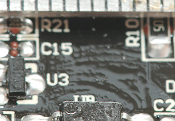
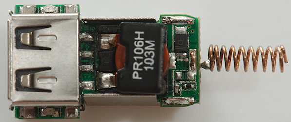
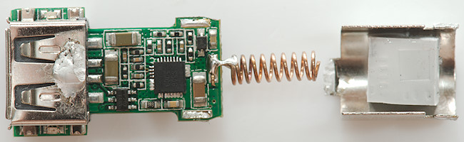
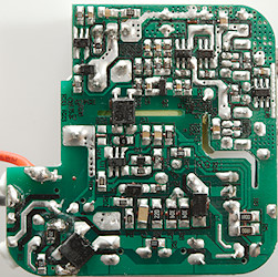
With the tape removed the bridge rectifier (BD1) can be seen. The low volt side is much more interesting, let see how much I can find out.
The largest part is the MPU (U2: R5F102AAA). There is a QC controller (U8: CHY100D) and the switcher for QC (U12: marked PMOQ / 08W / Z02C) with two rectifier diodes (D5, D6)
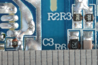
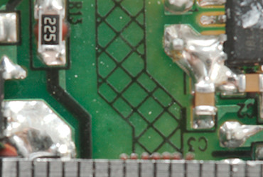
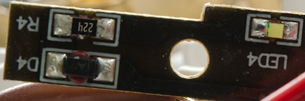
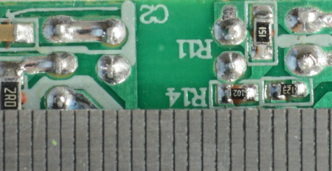
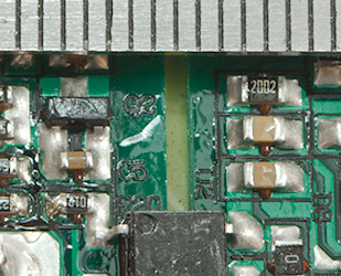
Resistors for current sense (R14, R14, R18, R19, R36, R37: R200), two in parallel for each output.
And some guessing:
Maybe U10 (Marked: HEE / ZE) is switching between auto coding and QC.
Probably auto coding chips (U3, U6, U13: Marked BTW), I wonder if they are controlled by the microprocessor.
Maybe a switch (U4, U7, U11: marked GUU / 5NF / 12) to control output power.
(U9: marked JCB / 4S3 / E)
R5F102AAA: Renesas MPU with flash memory, RL78/G12 Data flash provided, 30pin, 16kB rom, consumer -40°C ~ 85°C
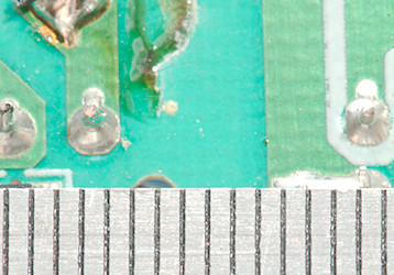
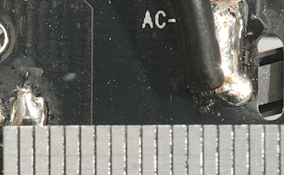
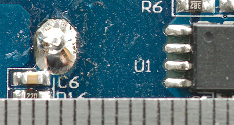
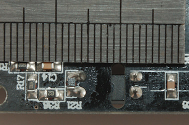
![DSC_0085]()
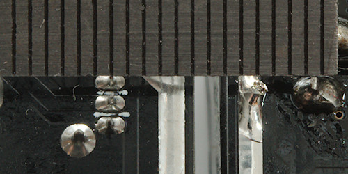
![DSC_0086]()
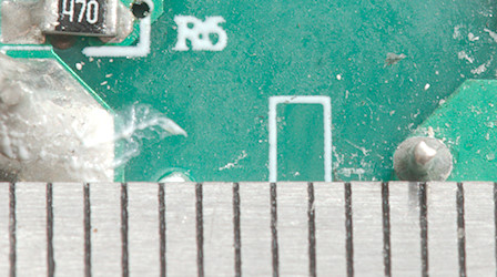
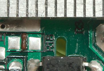
Safety distance looks good.
Testing with 2830 volt and 4242 volt between mains and low volt side, did not show any safety problems.
Conclusion
A charger that can show current and voltage for each output is interesting and has been seen before, but with graphing, multiple outputs and quick charge this device is more versatile that anything I have seen before.
There can be some good economic in using a phone for display, instead of mounting the display in the charger. The phone uses a high-resolution display and today most people have one, but I am not really impressed with the connection used. Some phones are lacking the audio jack and the usb connection will increase resistance on that output. A Bluetooth module would be a more modern solution. The app. do also loose the chart way to easy, some way for the app. to stay in the background and continue collecting would have been nice (This may not be possible due to the usage of the audio jack).
The precision is not very good, an external usb meter is much more precise
The total current is a bit low for a 3 output device, there is a lot of noise and I am missing auto coding on the outputs, my phone will only charger with 0.6A. The output voltage starts rather high and drops significantly when loaded.
In total I am not that impressed with the charger, it is a fairly good charger, but the analyzing part fails.
NotesIndex of all tested USB power supplies/chargersRead more about how I test USB power supplies/chargerHow does a usb charger work?