Forums:
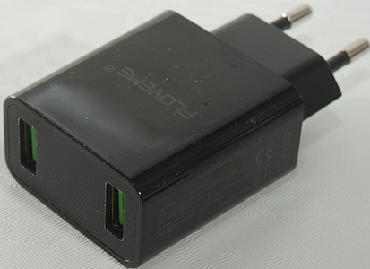
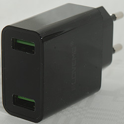
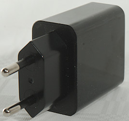
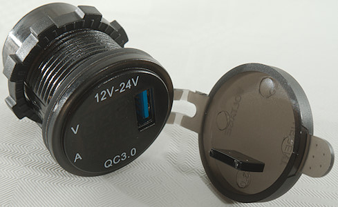
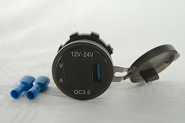
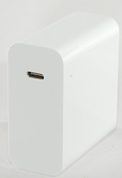
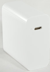
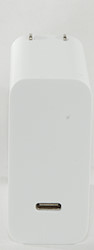
Qihang Fast Charger QH-Z03
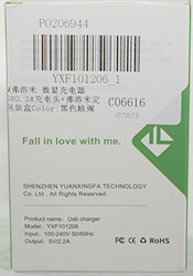
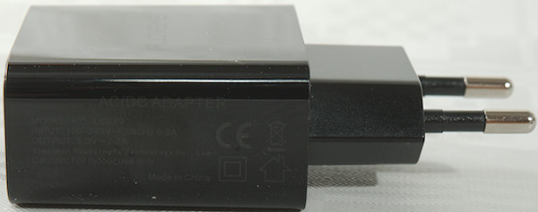
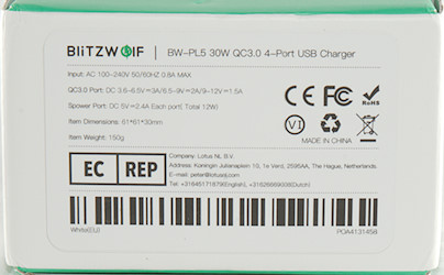
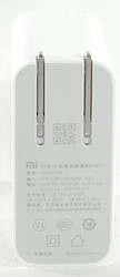
Official specifications:
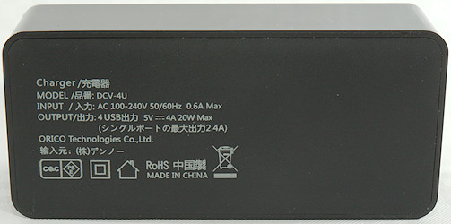
- Input voltage: 100-240V
- Output: 5V 3A, 9V 2A, 12V 1.5A


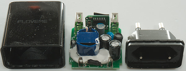
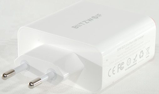
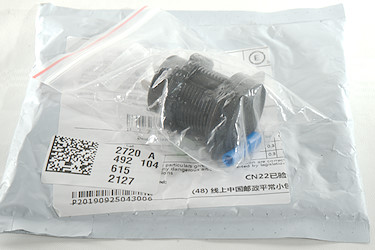
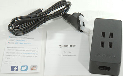
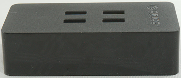
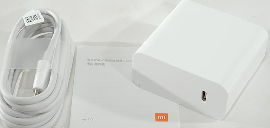
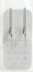
It arrived in a partial transparent plastic box.


Measurements
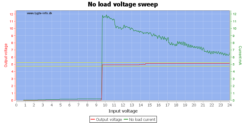
- Power consumption when idle is 0.05 Watt
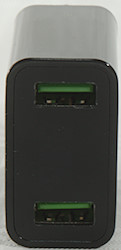
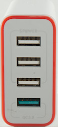
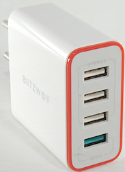
- USB output is auto coding with Apple 2.4A, Samsung, DCP and QC3
- Minimum QC3 voltage is 3.6V
- Weight: 35.7g
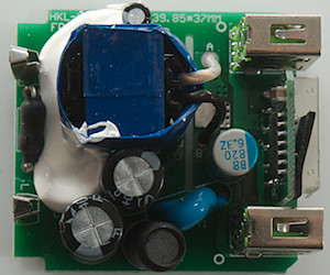
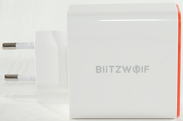
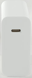
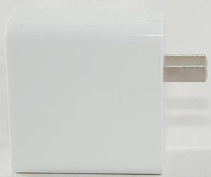
- Size: 75.6 × 36.6 × 23.7mm

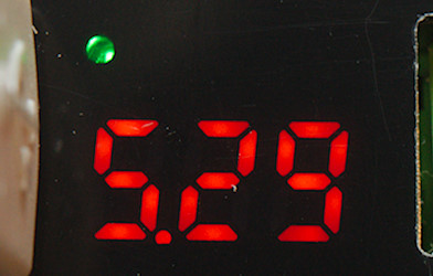
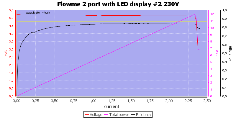
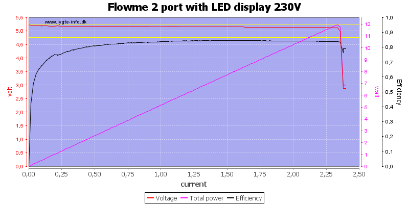
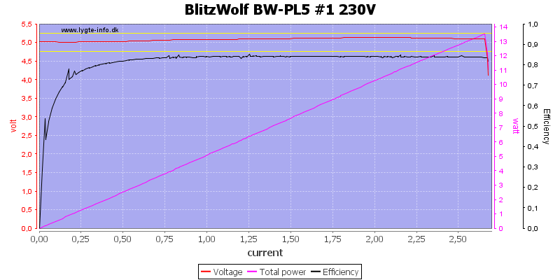
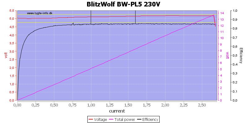
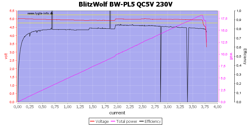
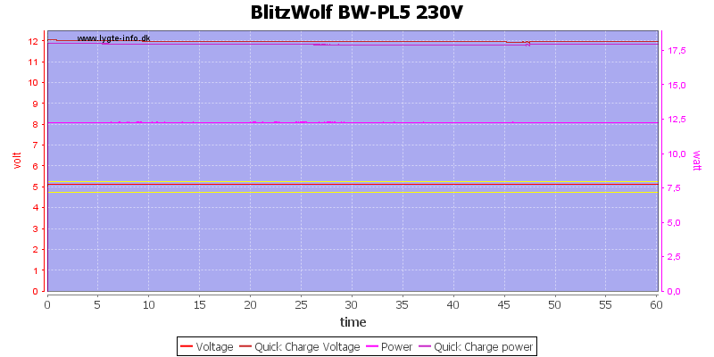
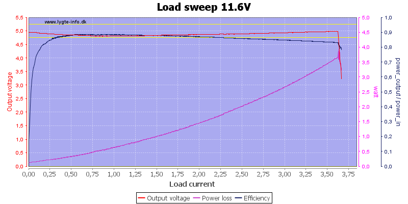
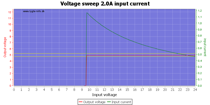
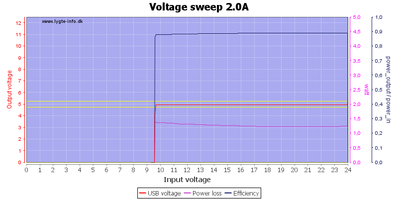
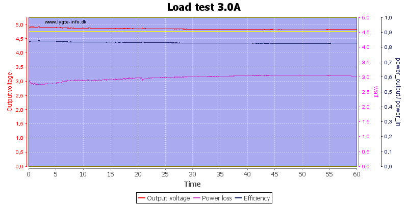
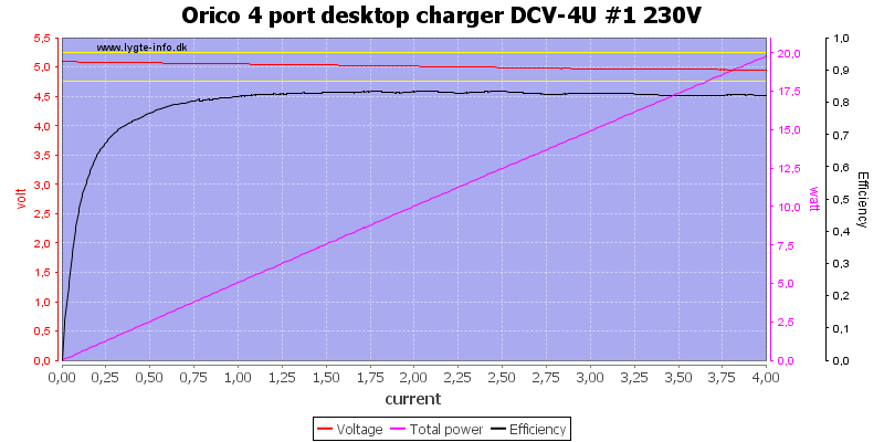
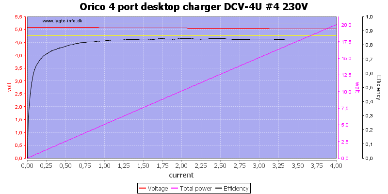
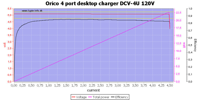
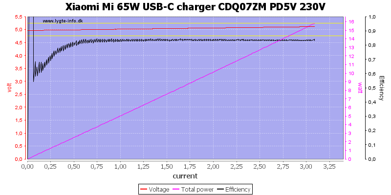
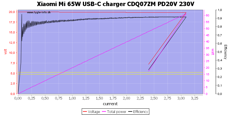
The charger is rated for 3A on 5V and deliver about 3.2A, this is fine.

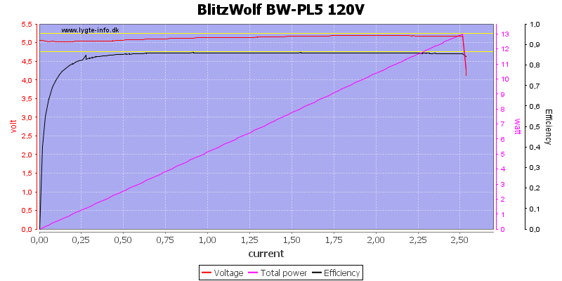
It works the same on 120VAC.

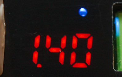
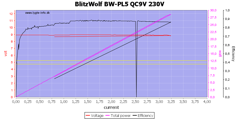
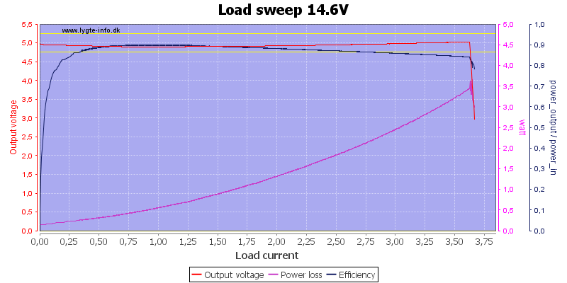
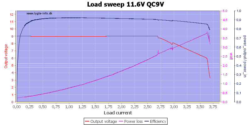
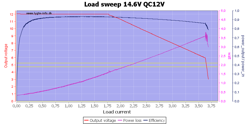
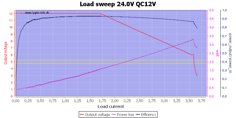
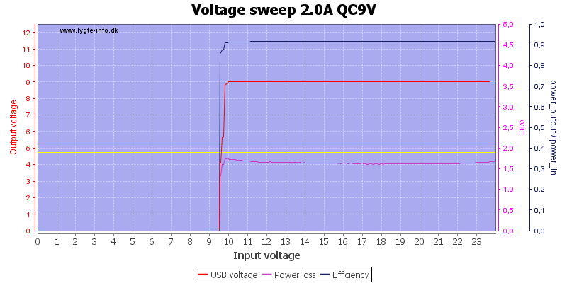
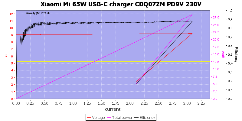
At 9V it matches the 2A rating very nicely.

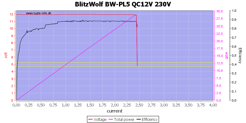
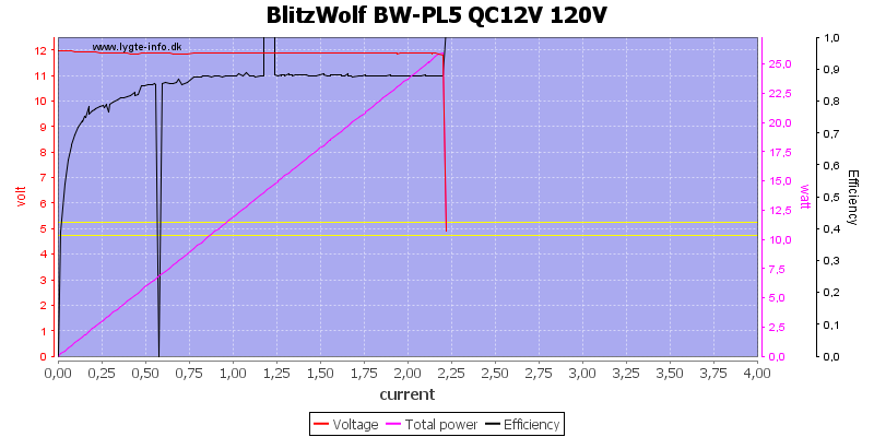
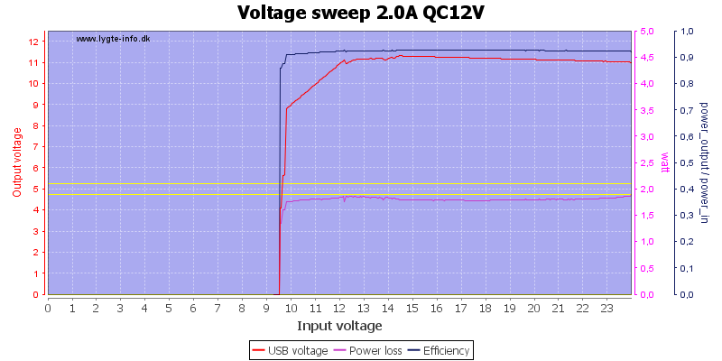
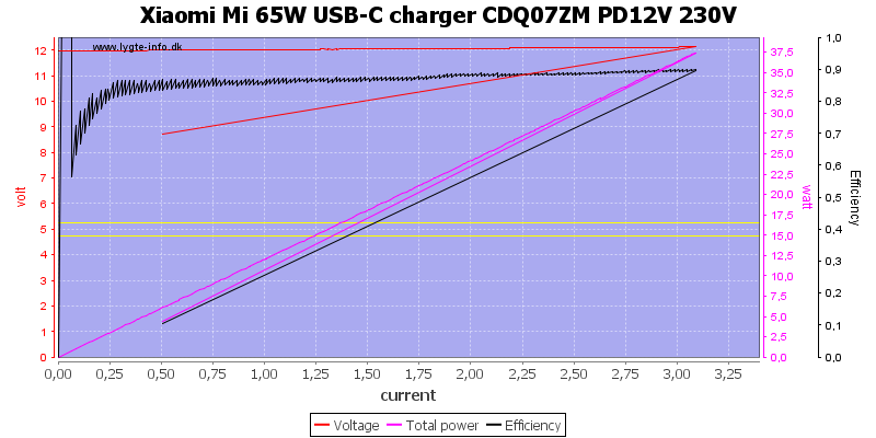
At 12V it is rather close to the 1.5A rating.

It looks better at 120VAC.

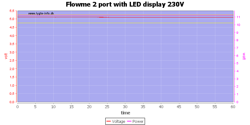
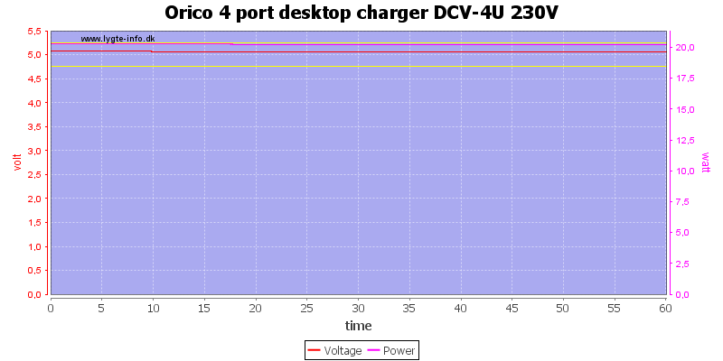
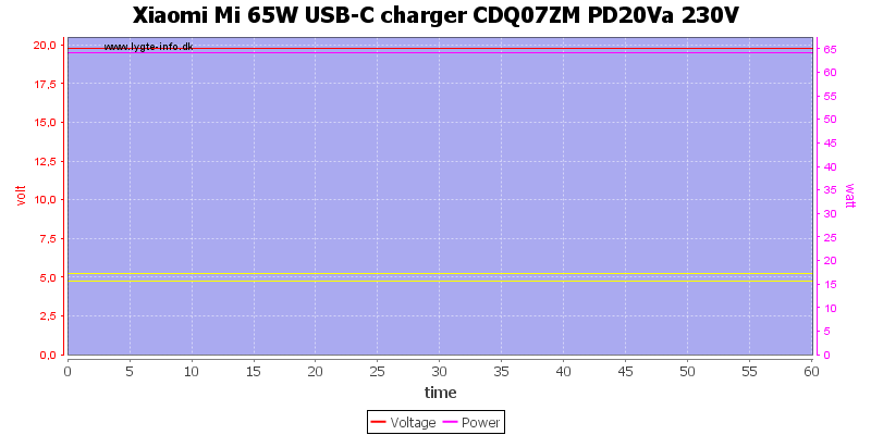
The overload protection must be temperature sensitive, it kicked in after 8 minutes at 2A load on 9V.

Reducing the current to 1.8A and it could handle a 1 hour test.
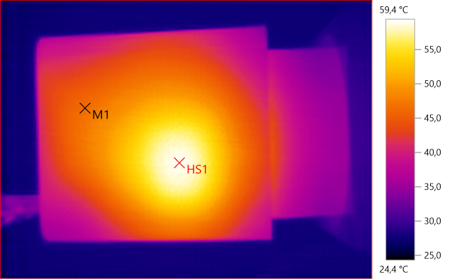
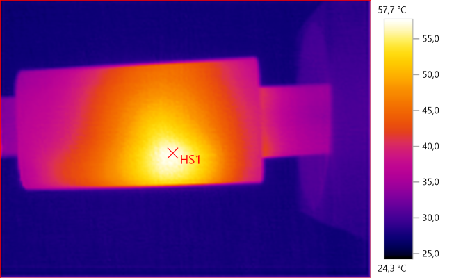
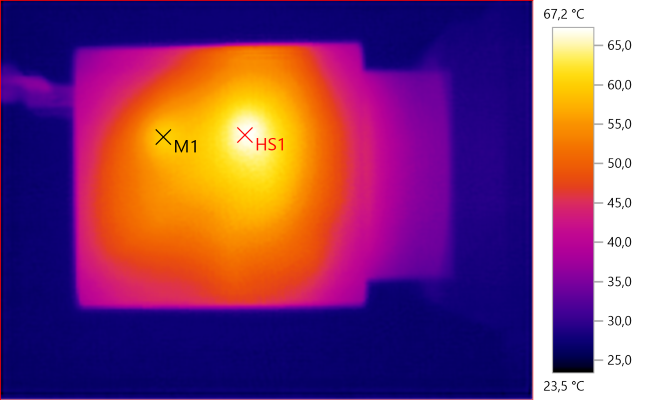
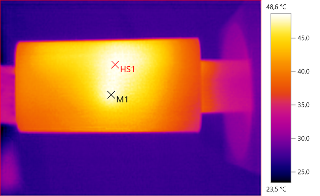
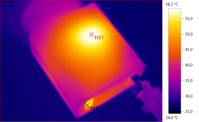
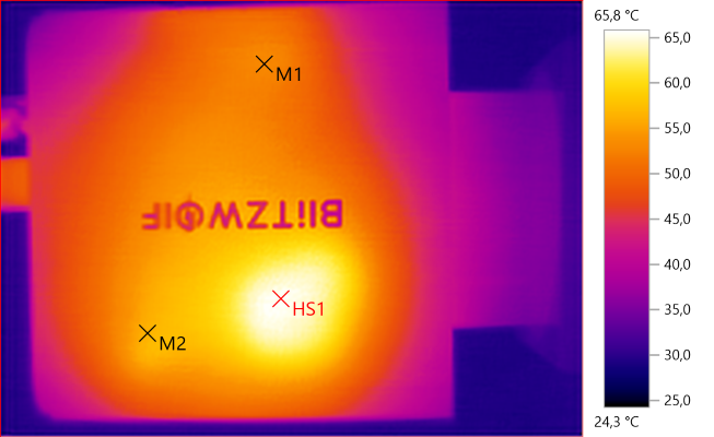
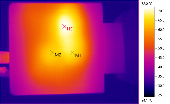
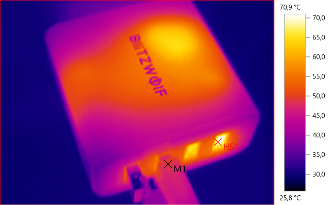
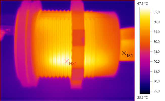
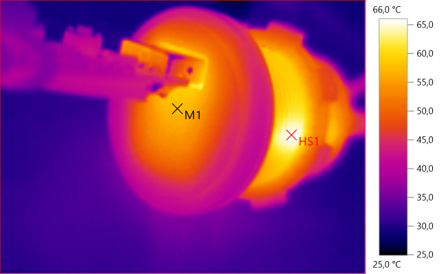
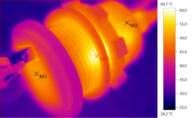
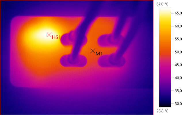
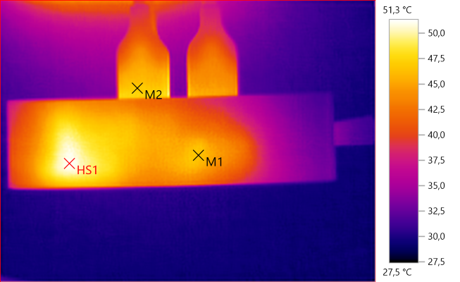
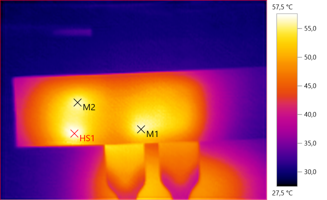
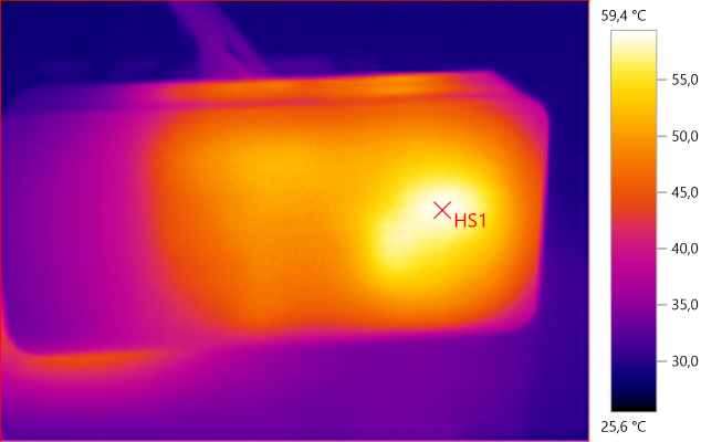
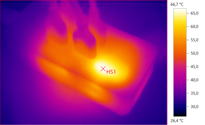
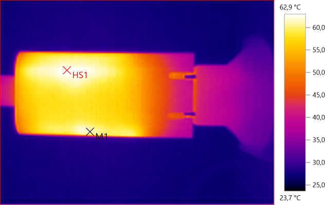
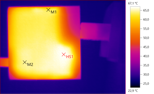
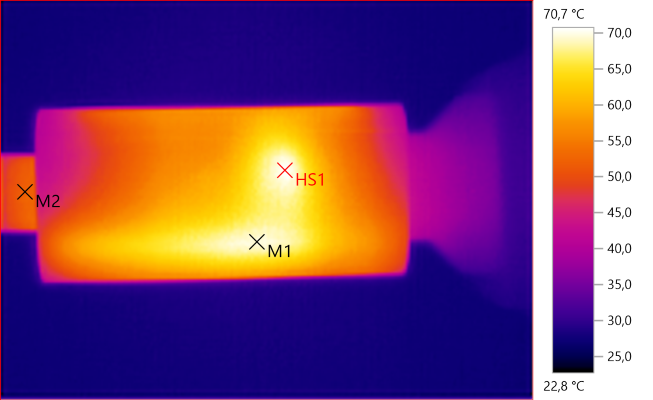
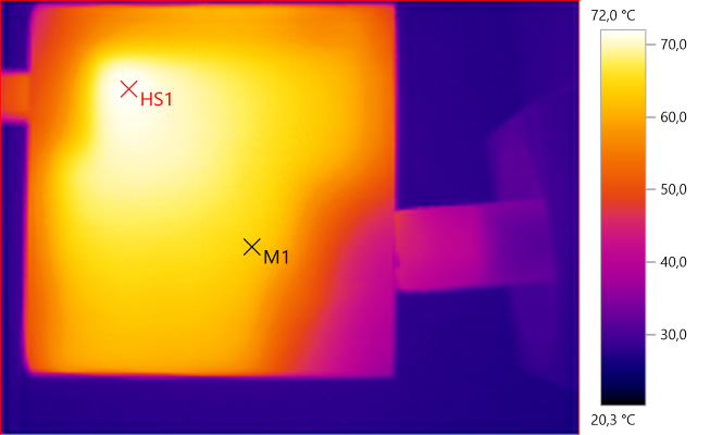
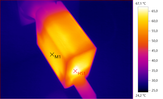
The temperature photos below are taken between 30 minutes and 60 minutes into the one hour test.

HS1: 73.7°C
HS1 is transformer.

M1: 56.4°C, HS1: 62.2°C

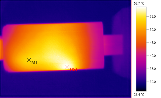
M1: 47.4°C, M2: 39.4°C, HS1: 50.5°C

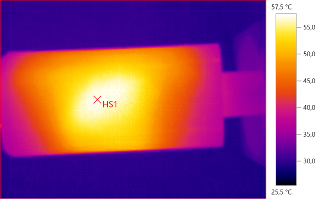
HS1: 57.4°C

HS1: 72.7°C

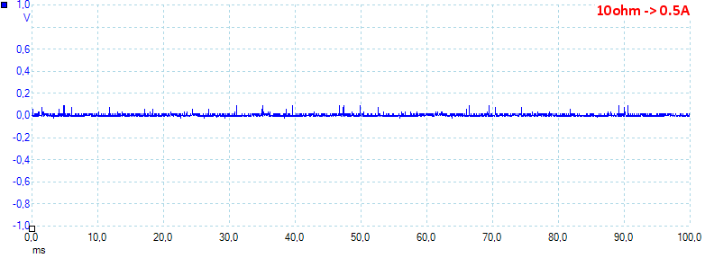
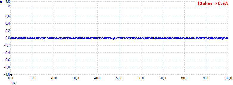
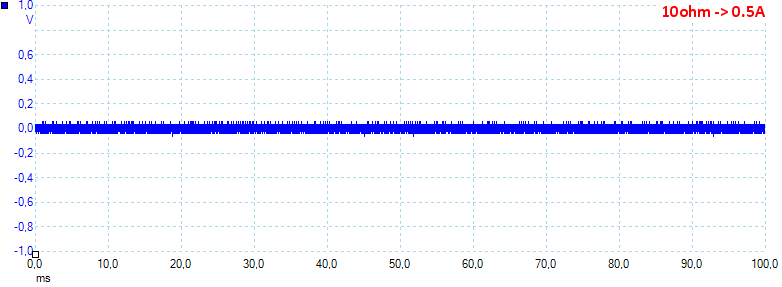
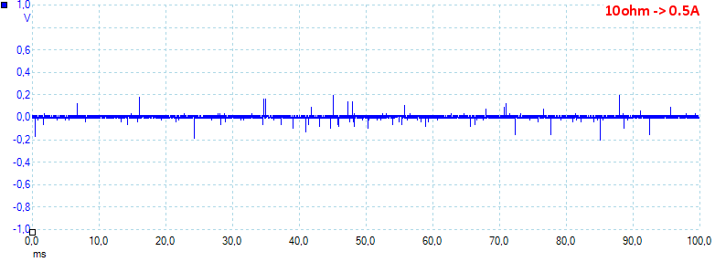
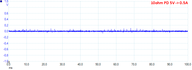
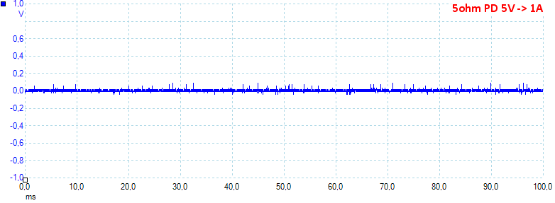
At 0.5A the noise is 48mV rms and 1835mVpp.

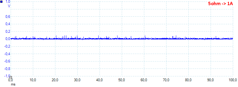
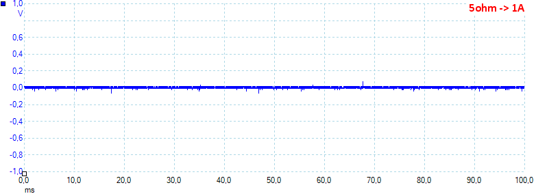
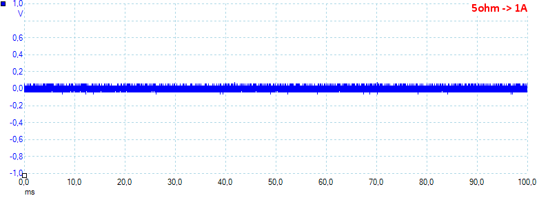
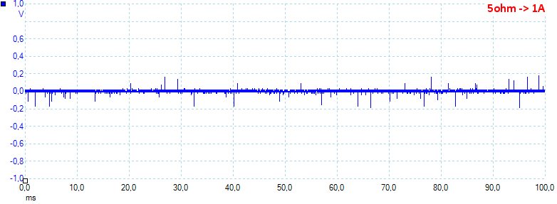
At 1A the noise is 42mV rms and 829mVpp.

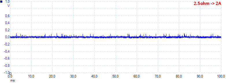
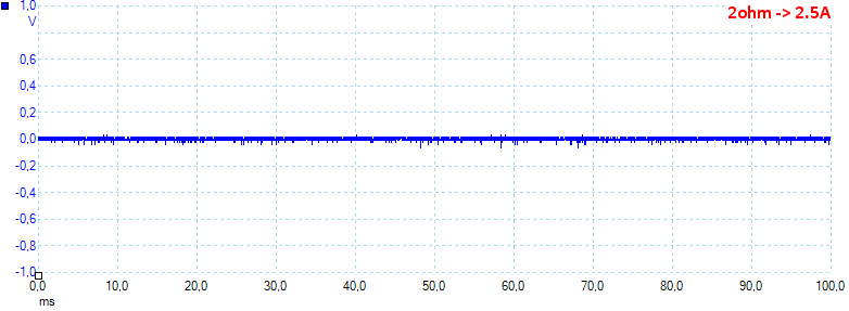
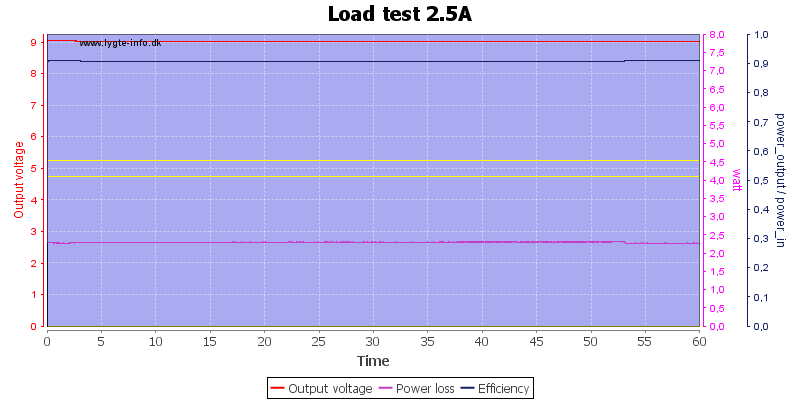
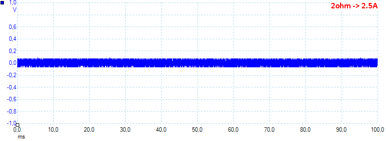
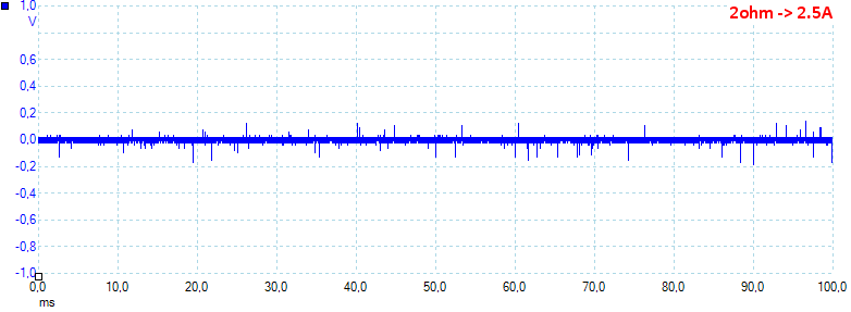
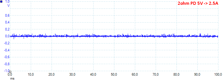
At 2.5A the noise is 54mV rms and 1421mVpp.

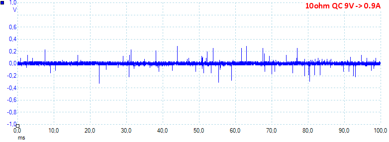
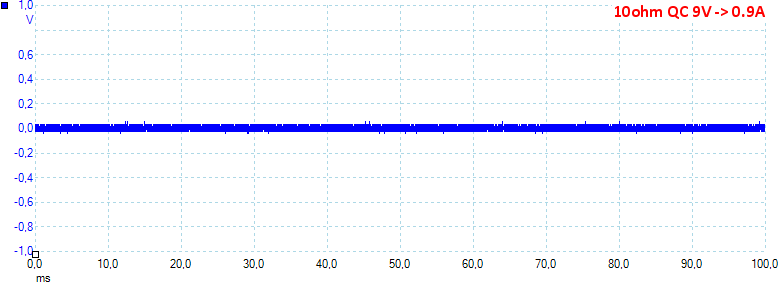
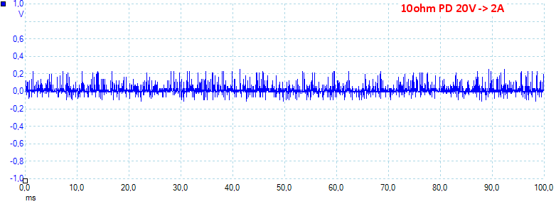
At 0.9A the noise is 49mV rms and 1156mVpp.

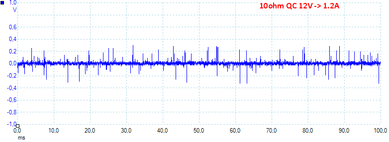
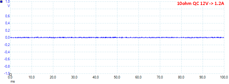
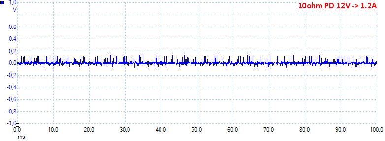
At 1.2A the noise is 69mV rms and 1165mVpp.
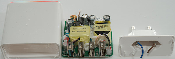
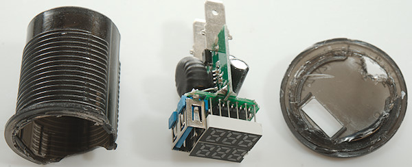
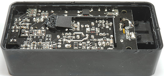
Tear down

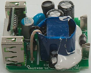
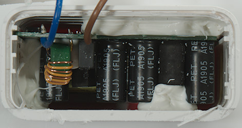
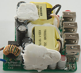
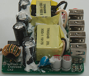
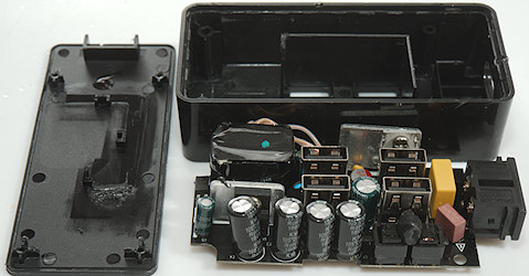
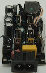
Putting a lot of pressure on the top of the charger with my vice made the lid pop out.

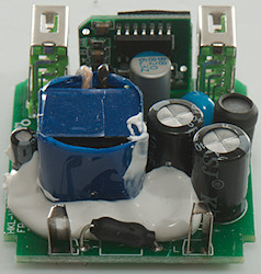
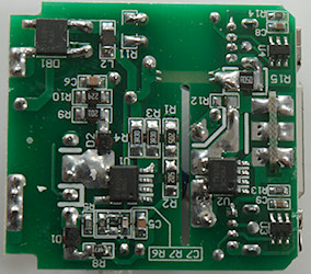
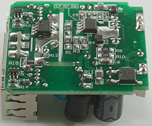
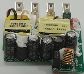
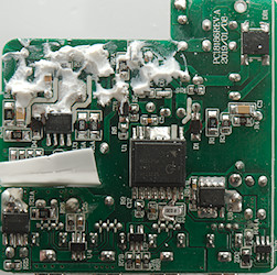
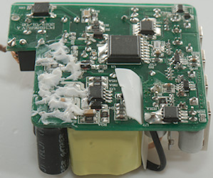
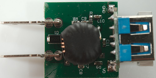
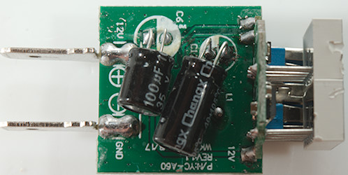
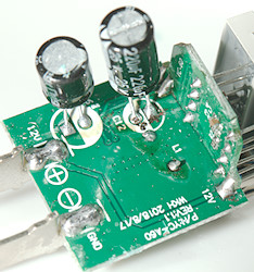
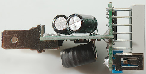
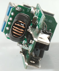
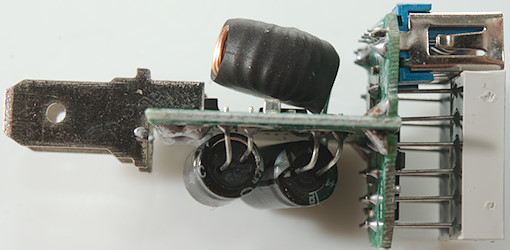
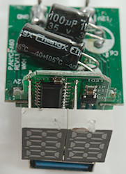
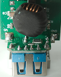
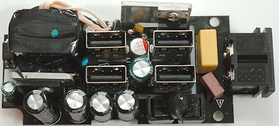
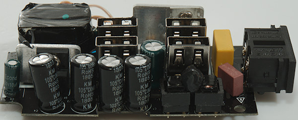
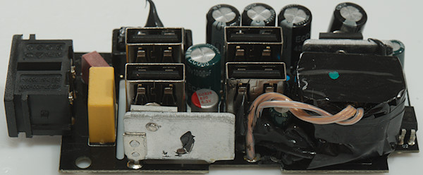
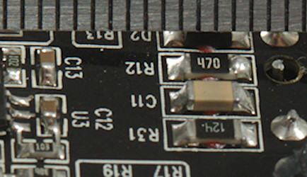
At the input is a fusible resistor in heatshrink, the two mains smoothing capacitors (C1 & C2) has a inductor (L1) between them. There is a safety capacitors (CY1) between mains and low volt side.


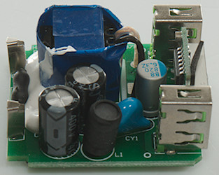
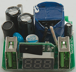
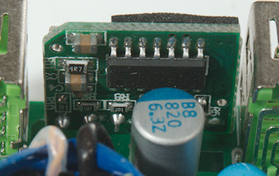
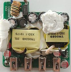
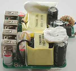
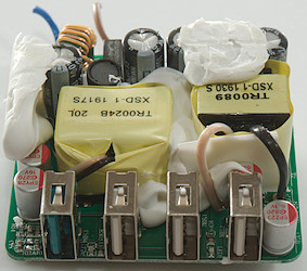
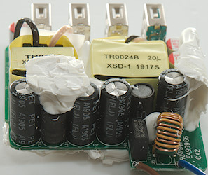
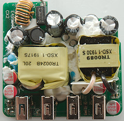
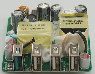
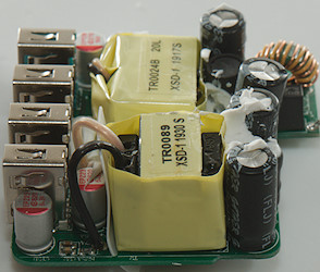
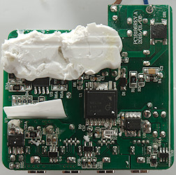
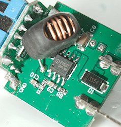
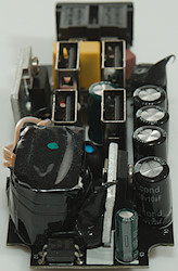
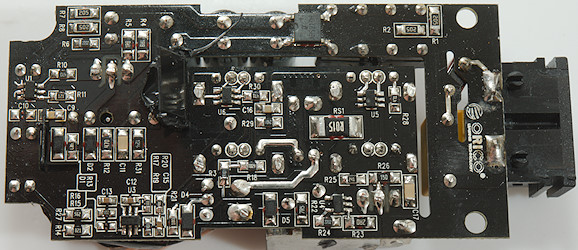
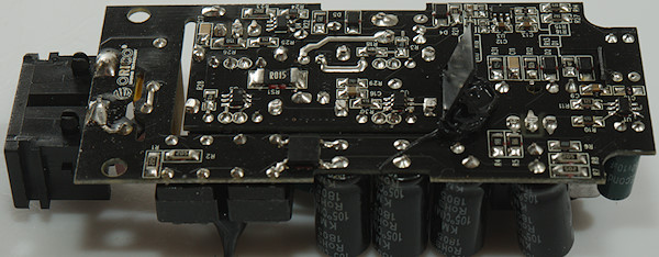
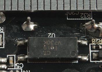
On this side is the bridge rectifier (BD1), the mains switcher (ATC9560), opto feedback, a rectifier diode (D3: probably DK5V85R1… synchronous rectifier), a QC controller (U3: Maybe LP103) and a reference (U4).


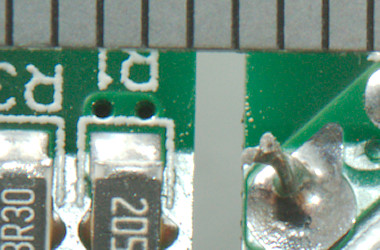
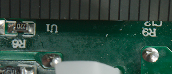
The distance between mains and low volt side is fine.
Testing with 2830 volt and 4242 volt between mains and low volt side, did not show any safety problems.
Conclusion
The charger is a fairly standard QC3 charger with good efficiency, the safety look fine. Like many cheap chargers it do not have any mains filtering, this means the radio emission it probably way above the legal limits.
Notes
The USB charger was supplied by a reader for review.
Index of all tested USB power supplies/chargers
Read more about how I test USB power supplies/charger
How does a usb charger work?
—
My website with reviews of many chargers and batteries (More than 1000): https://lygte-info.dk/